Encode and multiplex, register, and decode and error correction circuitry
a technology of error correction and register, applied in the direction of fault response, program control, instruments, etc., can solve the problems of reducing the dimension of microscopic transistors, exacerbate the risk of errors and reliability degradation,
- Summary
- Abstract
- Description
- Claims
- Application Information
AI Technical Summary
Benefits of technology
Problems solved by technology
Method used
Image
Examples
embodiment 800
[0090]FIG. 8 shows a vehicle electronic system embodiment 800 for increased endianess safety as further detailed in the other Figures. A microcontroller IC 810 such as in FIG. 4 is part of a controller area network (CAN) 820 subject to disturbance or interference 840Z from ignition system voltages, engine operations, tire static, etc. As detailed in the other Figures, the configuration embodiments, such as for endianess, can cooperate and perform even more reliably with CAN 820 circuitry such as I / O, Vss, vehicle ground GND, and control lines to various automotive subsystems that are coupled and associated with microprocessor 810.
[0091]Various SoC or IC embodiments are implemented in any integrated circuit manufacturing process such as different types of CMOS (complementary metal oxide semiconductor), SOI (silicon on insulator), SiGe (silicon germanium), organic transistors, and with various types of transistors such as single-gate and multiple-gate (MUGFET) field effect transistors...
embodiment 850
[0092]FIG. 9 shows a manufacturing process embodiment 850 to make integrated circuits for increased configuration safety such as for endianess. Beforehand, a design process produces a netlist of circuitry as described herein and then generates a physical layout database or pattern generation PG, which is also called a tape-out. In process 850, a step 860 fabricates the integrated circuit in a wafer fabrication facility according to the PG layout that provides e.g. key error-correcting logic for endianess configuration. A succeeding step 870 electronically programs nonvolatile OTP memory with the configuration. Step 880 then powers up the IC and executes a runtime automatic electronic diagnostic process for the configured status, such as endianess status, as described elsewhere hereinabove using e.g. a 3-step diagnostic. Step 880 executes production screening or testing of error-resistance and stability of the configuration, as well as other performances of the chip or system. If the...
embodiment 900
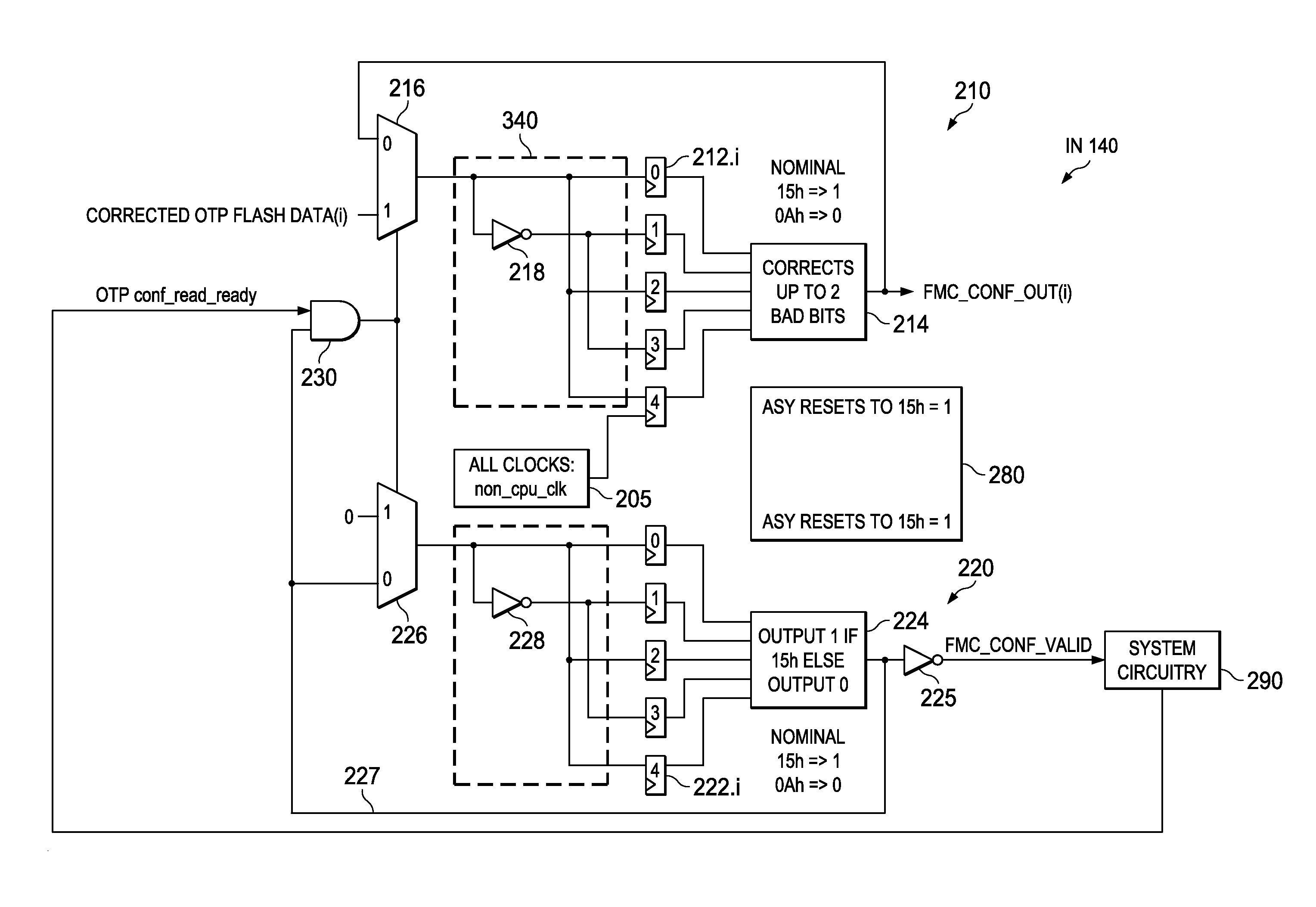
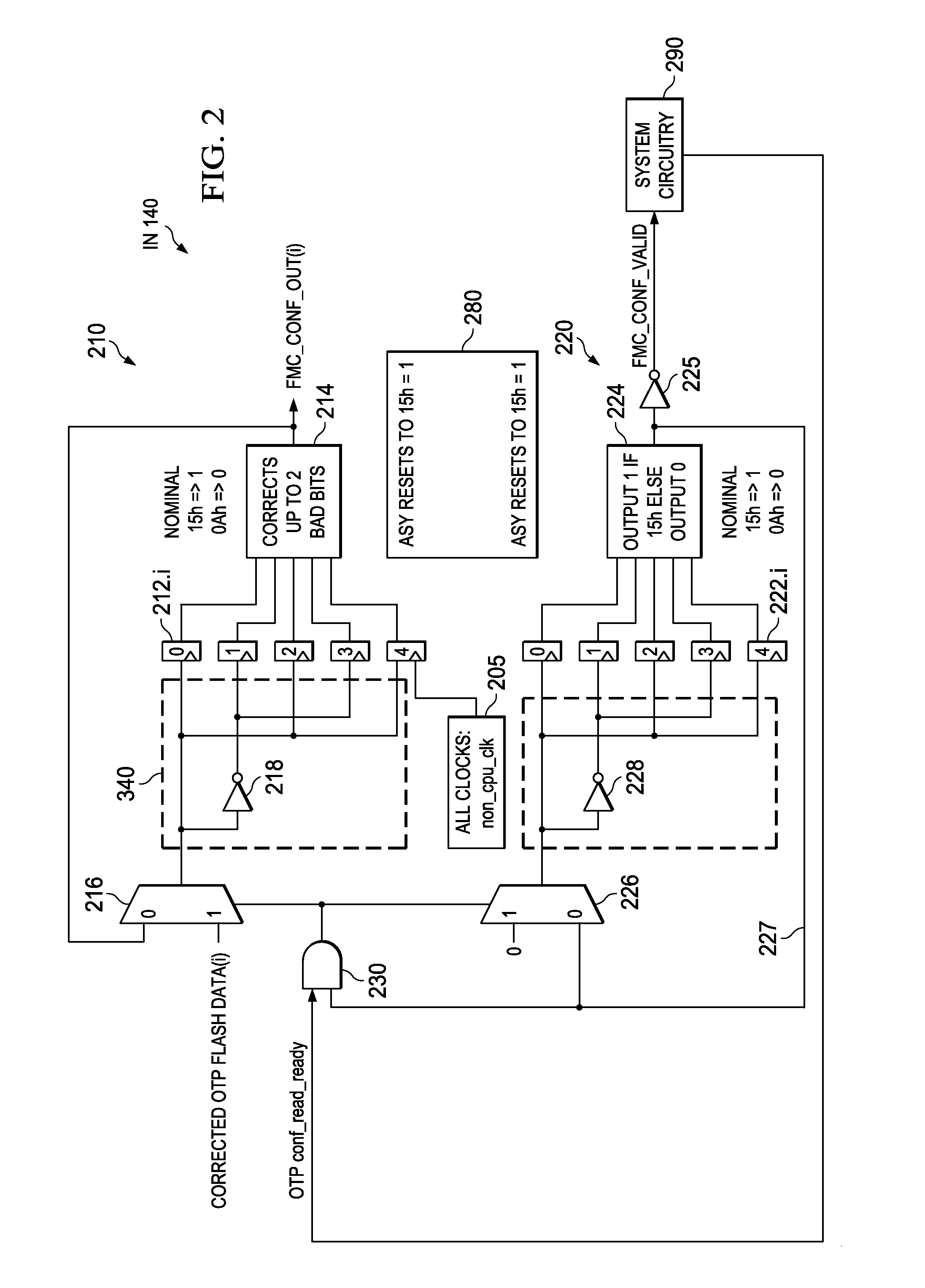
[0093]FIG. 10 shows a process embodiment 900 of electronic circuit operation for increased configuration safety such as for endianess. In the process 900, a step 910 reads a key value, and decodes the key into an enable (i.e., an enabling control signal) if the value supplied as the key is the expected value. Then a step 920 responds to the enable and reads a configuration input. A succeeding step 930 encodes at least one bit from the configuration and form a multi-bit encode value. Then a step 940 stores the multi-bit encode value, such as to a register 212 (360). A further step 950 decodes the value in the register using an error correcting method that delivers fewer bits, or even one bit, as a register decode value. In this way, when the multi-bit encode value is altered by fewer than a specified number of errors due to intervening interference, the register decode value delivered by step 950 is the same as if the multi-bit encode value were unaltered and had no errors introduced...
PUM
 Abstract
Description
Claims
Application Information
 - R&D
- Intellectual Property
- Life Sciences
- Materials
- Tech Scout
- Unparalleled Data Quality
- Higher Quality Content
- 60% Fewer Hallucinations
Browse by: Latest US Patents, China's latest patents, Technical Efficacy Thesaurus, Application Domain, Technology Topic, Popular Technical Reports.
© 2025 PatSnap. All rights reserved.Legal|Privacy policy|Modern Slavery Act Transparency Statement|Sitemap|About US| Contact US: help@patsnap.com


