
A yarn winding apparatus and an operation original location adjusting method

A technology of coiling device and origin position, which is applied in the directions of transportation and packaging, conveying filamentous materials, thin material processing, etc., and can solve the problems detected by photoelectric sensor, offset of the origin position of action part, and influence of coiling action, etc. , to achieve the effect of suppressing the increase in power consumption

Active Publication Date: 2013-04-03
MURATA MASCH LTD
View PDF8 Cites 2 Cited by
  • Summary
  • Abstract
  • Description
  • Claims
  • Application Information

AI Technical Summary

Problems solved by technology

[0004] Here, in the winding unit described in Japanese Patent Application Laid-Open No. 2011-16631, when repairing or the like is performed in the maintenance mode, the operator touches the operating portion of the winding unit, etc., and the position of the operating origin of the operating portion is shifted. Case
On the other hand, the photoelectric sensor described in Japanese Patent Application Laid-Open No. 2003-112854 is not capable of detecting the position of the origin of the action of each action part with a precise target, and there is a range in the detection range.
Therefore, in the maintenance mode, if the operating part of the winding unit deviates within the above-mentioned detection range, the deviation cannot be detected by the photoelectric sensor.
In addition, if such a deviation in the detection range of the photoelectric sensor occurs, switching from the maintenance mode to the normal operation mode and restarting the winding of the yarn may affect the winding operation.

Method used

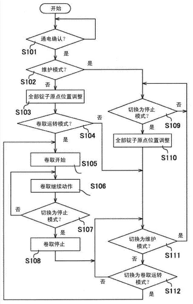

Image

  • A yarn winding apparatus and an operation original location adjusting method
  • A yarn winding apparatus and an operation original location adjusting method
  • A yarn winding apparatus and an operation original location adjusting method

Examples


Embodiment Construction

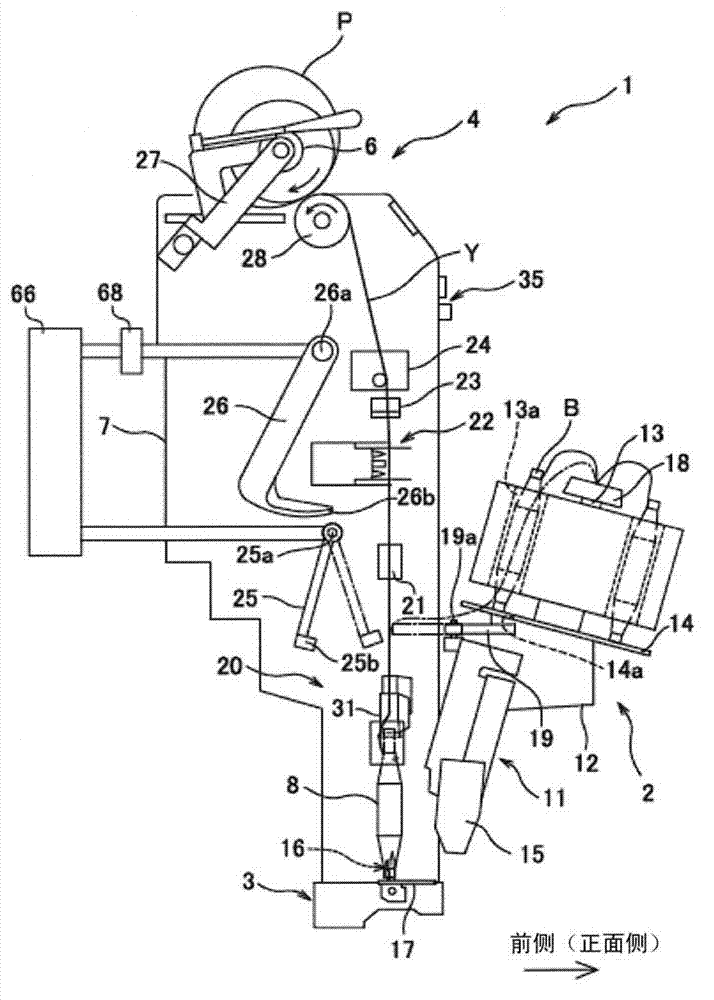
[0041] Next, embodiments of the present invention will be described. This embodiment is applied to an automatic winder including a plurality of winding units (yarn winding devices) that wind the yarn unwound from the yarn supply bobbin onto the winding bobbin to form a winding package. An example of invention. The automatic winder has a structure in which winding units forming one package are arranged in multiple rows in one direction. figure 1 It is a side view of one winding unit of the automatic winder. In addition, in figure 1 In , the right side is defined as the front side (front side) where the operator works on the winding unit 1 , and the left side is defined as the opposite rear side (back side).

[0042] Such as figure 1 As shown, the winding unit 1 includes a bobbin supply device 2, a bobbin support portion 3, and a yarn winding portion 4, respectively. In addition, the operation of the winding unit 1 is controlled by the control device 50 . Further, the wind...


PUM


Abstract

A yarn winding apparatus and an operation original location adjusting method are provided, the winding unit as an operation unit which includes the opening and closing member, the guide screw, bolt, the movable cylinder, connector means for guiding the upper yarn catching member, the lower yarn capture guide member and the gate line, so that these movements and operation of winding the yarn winding operation mode, and for maintenance operation portion is stopped leaving a pattern in maintenance mode operation. In a winding unit, in the winding from the maintenance mode to the operation mode for the take-up unit is the operation of the operation unit to adjust the home position, and then starts winding the yarn. In addition, when having a plurality of winding units of an automatic winder a power is turned on, all of the winding unit, for the operation of the operation unit to adjust the origin position. A plurality of operation unit to adjust the operation of the home position is not the same time, and each part to a predetermined order.

Description

technical field [0001] The present invention relates to a yarn winding device for winding a yarn unwound from a yarn supply bobbin, and a method for adjusting the position of an operating origin of the yarn winding device. Background technique [0002] The winding unit (yarn winding device) described in Japanese Patent Application Laid-Open No. 2011-16631 can selectively perform a normal winding mode (winding operation mode) for performing normal winding operations, and a One of the maintenance modes in the section. And, when a malfunction occurs during the operation in the normal winding mode, the operator performs necessary repairs, etc. after switching from the normal winding mode to the maintenance mode, and switches from the maintenance mode when the repairs, etc. are completed. In the normal winding mode, yarn winding is started again. [0003] In the yarn winding machine described in Japanese Patent Application Laid-Open No. 2003-112854, an origin detector of the pi...

Claims


Application Information

Patent Timeline
Patent Type & Authority Applications(China)
IPC IPC(8): B65H63/00
Inventor 川元谦治
Owner MURATA MASCH LTD
Learn More