Silica container and method for producing the same

a technology of silica glass and containers, which is applied in the field of silica containers, can solve the problems of high energy consumption, high temperature and processing temperature of silica glass, and high price of silicon tetrachloride, and achieves high dimensional precision, low energy consumption, and high durability.

Active Publication Date: 2014-12-23
SHIN ETABU QUARTZ PRODS
View PDF35 Cites 0 Cited by
  • Summary
  • Abstract
  • Description
  • Claims
  • Application Information

AI Technical Summary

Benefits of technology

The present invention describes a method for producing a silica container that can reduce the harmful effects of gas molecules released during use. This is achieved by suppressing gas molecules dissolved in the container during production. The resulting silica container has high precision and durability, and is able to prevent impurity contamination. This method offers a low energy consumption, high productivity, and low cost for producing silica containers. The same invention also provides a cheap silica container with high precision and durability, capable of avoiding impurity contamination and reducing harmful effects of gas molecules.

Problems solved by technology

However, an expensive compound such is silicon tetrachloride must be used as a raw material for a silica glass used in these silica articles; on top of that, melting temperature and processing temperature of a silica glass is extraordinary high (about 2000° C.
), thereby leading to a high energy consumption, and this in turn to causing enormous emission of carbon dioxide, which is considered to be one of the global warming gases.
In these sol-gel methods, however, not only there were problems in a dimensional precision and a durability of the produced silica glass but also production cost thereof was not so cheap.
In these conventional slip casting methods, however, shrinkage of a molded article in drying and sintering processes is so large that a thick silica glass article with a high dimensional precision could not be obtained.
Accordingly, there are problems as mentioned above in the method for producing a silica glass article from a powdered raw material.
In these methods, however, there has been a problem of a high cost because a highly purified powdered quartz is used.
In addition, when a silica crucible is produced by a conventional method for manufacturing of a silica glass article and then used for growing of a silicon single crystal, there has been a problem such that much of gaseous bubbles are incorporated into a grown silicon single crystal.

Method used


Image

  • Silica container and method for producing the same
  • Silica container and method for producing the same
  • Silica container and method for producing the same

Examples


example 1

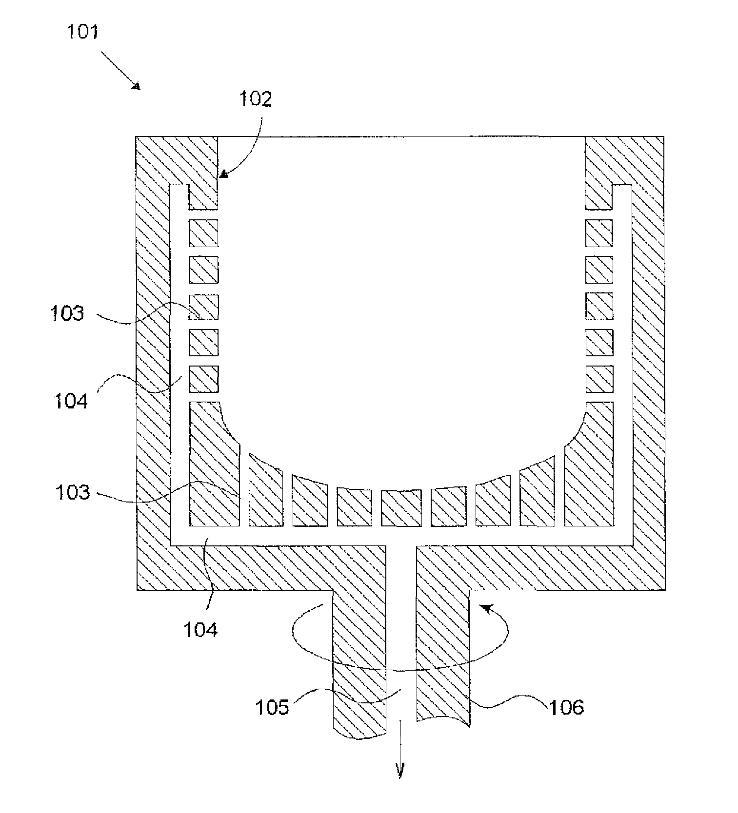
[0137]According to the method for producing a silica container of the present invention as shown in FIG. 1, the silica container is produced as following.

[0138]Firstly, the first powdered raw material 11 was prepared as following (a part of Step 1).

[0139]A natural silica stone (100 kg) was prepared, heated in an air atmosphere at 1000° C. for 10 hours, poured into a pool of pure water, and then cooled quickly. After drying, the stone was crushed by a crusher to make total weight 90 kg of the powdered silica (the powdered natural silica stone) having particle diameter in the range from 30 to 600 μm and silica purity (SiO2) of 99.999% by weight.

[0140]As the additive 12 to be added to the first powdered raw material 11, an aqueous aluminum nitrate solution was prepared (a part of Step 1). This was mixed with the first powdered raw material 11 and dried to make the powder mixture 31 (Step 2). Concentration of Al in the first powdered raw material 11 was set so as to be 50 ppm by weight....

example 2

[0147]The same procedures as Example 1 were followed except that the atmospheric gas was changed to a nitrogen gas containing 3% by volume of a hydrogen gas (97% by volume of the nitrogen gas concentration) in the step of forming the silica substrate 51 from the preliminarily molded article 41 (Step 4) and the second powdered raw material 21 was changed to a powdered synthetic cristobalite.

example 3

[0148]The same procedures as Example 1 were followed except that the added amount of aluminum nitrate into the first powdered raw material 11 was changed to 100 ppm by weight as the Al concentration, the atmospheric gas in the step of forming the silica substrate 51 from the preliminarily molded article 41 (Step 4) was changed to a nitrogen gas containing 10% by volume of a hydrogen gas (90% by volume of the nitrogen gas concentration), and the particle diameter of the second powdered raw material 21 was changed to in the range from 50 to 300 μm.


PUM

PropertyMeasurementUnit
processing temperatureaaaaaaaaaa
temperatureaaaaaaaaaa

Abstract

Producing a silica container includes forming a powder mixture by adding an Al compound or a crystal nucleating agent into a first powdered raw material; preliminarily molding to an intended shape by feeding the powder mixture to an inner wall of an outer frame while rotating the outer frame having aspiration holes; forming a silica substrate; and forming a transparent silica glass layer on an inner surface of the silica substrate, wherein the preliminarily molded article is degassed by aspiration from a peripheral side and heated from inside the preliminarily molded article at high temperature making a peripheral part of the preliminarily molded article to a sintered body while an inner part to a fused glass body, and a second powdered raw material having a higher silica purity than the first powdered raw material is spread from inside the silica substrate and heated from the inside at high temperature.

Description

[0001]This is a Division of application Ser. No. 13 / 054,909 filed Jan. 19, 2011, now granted U.S. Pat. No. 8,420,191 which in turn is a National Phase of Application No. PCT / JP2010 / 002026 filed Mar. 23, 2010. The disclosure of the prior applications is hereby incorporated by reference herein in its entirety.TECHNICAL FIELD[0002]The present invention relates to a silica container mainly comprised of a silica and to a method for producing it, and in particular, relates to a silica container with a low cost, a high dimensional precision, and a high durability and to a method for producing it.BACKGROUND ART[0003]A silica glass is used for a lens, a prism and a photomask of a photolithography instrument in manufacturing of a large-scale integrated circuit (LSI), for a TFT substrate used for display, for a tube of a ultraviolet lamp or an infrared lamp, for a window material, for a reflection plate, for a cleaning container in a semiconductor industry, for a container for melting of a sil...

Claims


Application Information

Patent Timeline
Patent Type & Authority Patents(United States)
IPC IPC(8): C30B35/00B32B1/02C30B29/06C03B19/00C03B19/06C03B19/09C03C17/02C30B15/10
CPCC30B15/10C30B35/002C30B29/06C03B19/095C03B19/09Y10T428/1317Y10T428/131Y10T428/13Y02P40/57C03B20/00
Inventor YAMAGATA, SHIGERUUSUI, TOMOMI
Owner SHIN ETABU QUARTZ PRODS
Why Eureka
Try Eureka