Load bearing implants

a technology of load bearing implants and rods, applied in the field of implants, can solve the problems of bone thinning, bone may not fuse, and the elastic modulus of rods is very different from that of bone, so as to reduce excessive loading of bone tissue, prevent the generation of wear debris, and improve the compliance of elastic modulus with bone tissu

Active Publication Date: 2014-07-15
SIDEBOTHAM CHRISTOPHER G
View PDF15 Cites 2 Cited by
  • Summary
  • Abstract
  • Description
  • Claims
  • Application Information

AI Technical Summary

Benefits of technology

[0024]e. said proximal portion having a plurality of modulus decreasing features including longitudinal, inclined stress reducing cuts or slots thereby increasing load transfer to the bone area in the proximal region and preventing long term bone resorption;
[0028]whereby the combination of cuts or slots in the distal portion and central cylindrical aperture allow progressive flexing of the distal end, thereby minimizing excessive loading of the bone tissue, and appropriate selection of slots, depth of slots and spacing between slots prevents metal to metal contact on the adjacent surfaces of the cuts or slots during flexure, preventing generation of wear debris.

Problems solved by technology

This results in bone thinning after the implant has healed.
However, the elastic modulus of the rods is very dissimilar to that of bone and the bone may not fuse to the implant due to the absence of a porous bone ingrowth surface.
Application of any compressive force to the implant results in further expansion of the twisted rods resulting in permanent enlargement of the bone cavity, which will dislodge the implant.
When the implant is flexed, the distal portion of the implant still carries all of the flexural load and therefore does not prevent bone thinning.
This means that the thickness of the distal end decreases to very small value near the distal tip and may permanently deform the implant within the bone after insertion failing to provide adequate support during implant healing.
Besides, the permanently deformed tip of the implant may create enormous pain to the patient.
Since the control rod is held in place securing the spring, any movement in these attachment means will result in unsupported non recoverable movement of the spring.
The '001 patent disclosure does not provide a stem with a proximal potion having bone ingrowth coating and a distal end having a central cylindrical aperture and a helical slot cut in the outer surface to allow flexing of the stem at its distal end.

Method used


Image

  • Load bearing implants
  • Load bearing implants
  • Load bearing implants

Examples


Embodiment Construction

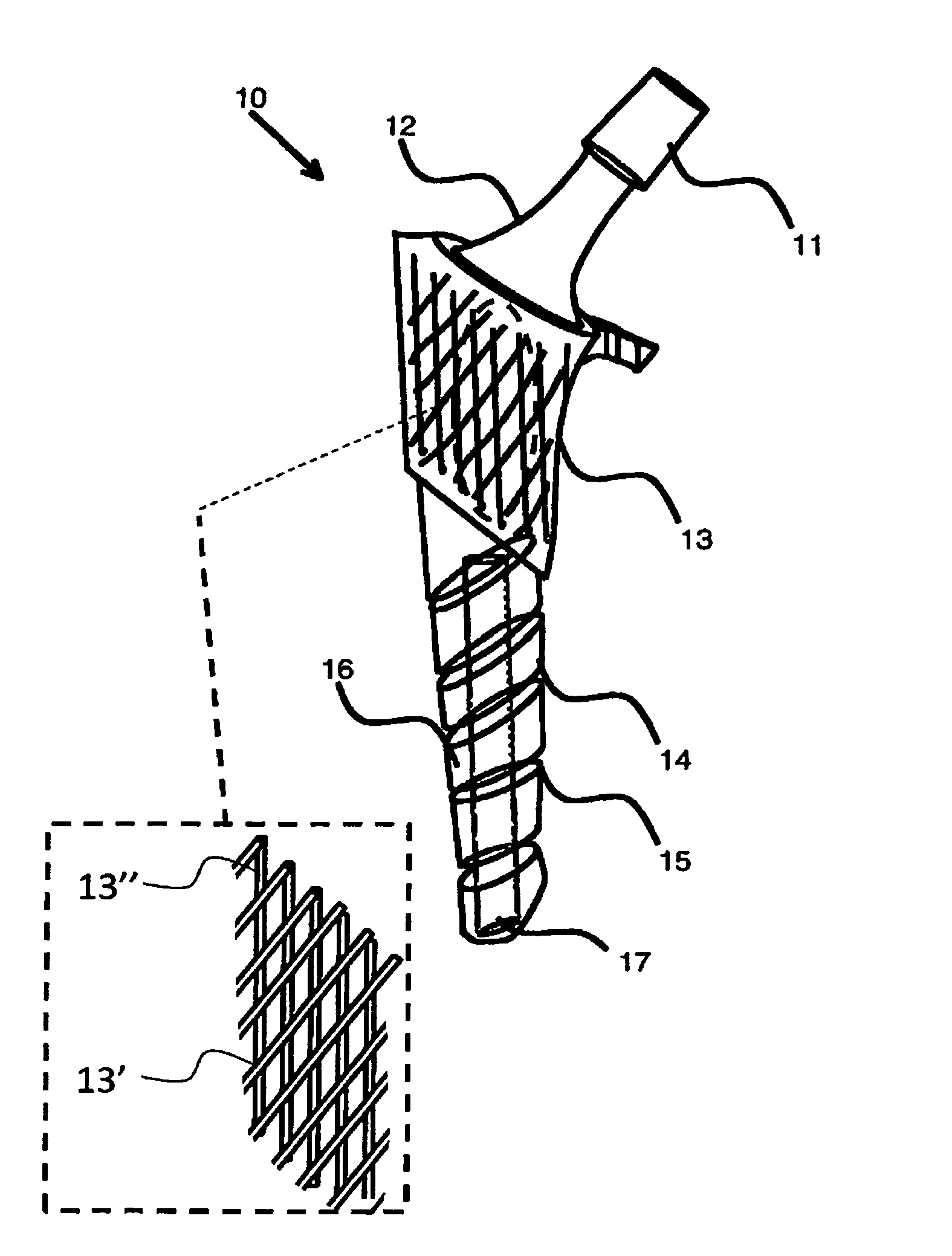
[0039]There are many implants designed to replace the articular surface of the human joints. These implants include hip, knee, elbow, shoulder and ankle replacements. The implant designs address two basic principles: (i) replacing the bearing surface of the joint for motion; and (ii) providing a method of fixing the implant to the body. The former design feature has evolved over the past fifty years to include various metals, plastics, ceramics and coatings, which provide low-friction movement with minimal generation of wear debris. These bearing surfaces include a cobalt chrome alloy against ultra high molecular weight polyethylene (UHMWPE), titanium nitride coated metals against UHMWPE, ceramic against ceramic, metal against metal and combinations of these. The results for these bearing surfaces continue to improve the longevity of these implant replacements. Wear debris has been shown to cause bone resorption leading to loosening of the implant from the bone. The latter design fe...


PUM


Abstract

A load bearing implant comprising a femoral implant stem made from a bio-compatible metal having an elastic modulus far greater than that of natural bone. When the implant heals within a bone cavity, the implant essentially carries substantially the entire load. Transfer of load to the surrounding bone tissue is lost due to lack of use after healing. Flexing a stiff implant applies a large load at the implant distal end. The bone cortex is thereby allowed to thicken, causing thigh pain long after implant healing. The femoral implant has a bone ingrowth coating on the proximal end, allowing firm attachment of the implant in the bone cavity. The distal end has a central aperture and a helical machined groove that permits flexing of the distal portion of the femoral implant stem. This flexing occurs in a manner similar to surrounding bone tissue, preventing thigh pain.

Description

BACKGROUND OF THE INVENTION[0001]1. Field of the Invention[0002]The present invention relates to implants; and more particularly to an implant that has flexural characteristics and load bearing qualities similar to a natural bone thereby preventing bone loss surrounding the implant due to lack of bone load bearing requirements.[0003]2. Description of the Prior Art[0004]Implants are generally made from bio-compatible materials such as titanium alloys or cobalt chromium alloys. These metallic implants have very high elastic modulus as compared to bone tissue. As a result, any load that is applied is almost entirely carried by the high elastic modulus material sparing the bone of its load bearing function. This results in bone thinning after the implant has healed. A number of prior art patents disclose attempts to solve this problem.[0005]U.S. Pat. No. 4,743,263 to Petrtyl et al. discloses an adaptable isoelastic hip-endoprosthesis. The adaptable isoelastic hip endoprosthesis comprise...

Claims


Application Information

Patent Timeline
Patent Type & Authority Patents(United States)
IPC IPC(8): A61F2/36A61F2/30
CPCA61F2002/3694A61F2002/30968A61F2/389A61F2002/30769A61F2002/30822A61F2002/30289A61F2/4059A61F2/3676A61F2/3601A61F2/3859A61F2002/30566A61F2002/3692A61F2/3094A61F2002/30594A61B17/72A61F2/3662A61B17/80H02G11/02B65H75/40A61F2002/30593
Inventor SIDEBOTHAM, CHRISTOPHER, G.
Owner SIDEBOTHAM CHRISTOPHER G
Why Eureka
Try Eureka