Laminate for dye-sensitized solar cell, electrode for dye-sensitized solar cell and method for producing it

a solar cell and dye-sensitized technology, applied in the direction of electrochemical generators, sustainable manufacturing/processing, final product manufacturing, etc., can solve the problems of limited installation conditions of solar cells containing glass supports, inability to sintered porous semiconductor layers at a sufficiently high temperature, and heavy glass. , to achieve the effect of high photovoltaic power generation efficiency, high durability and flexibl

Active Publication Date: 2013-12-10
TOYOBO CO LTD
View PDF31 Cites 0 Cited by
  • Summary
  • Abstract
  • Description
  • Claims
  • Application Information

AI Technical Summary

Benefits of technology

[0078]According to the invention, there are provided a laminate for dye-sensitized solar cell and an electrode for dye-sensitized solar cell capable of producing highly-durable and flexible, dye-sensitized solar cells that have high photovoltaic power generation efficiency and are free from a problem of time-dependent photovoltaic power generation performance degradation.INDUSTRIAL APPLICABILITY
[0079]The laminate for dye-sensitized solar cell of the invention is well workable and its interlayer adhesiveness is high, and the laminate is useful as a part of an electrode for dye-sensitized solar cell. Using it, a dye-sensitized solar cell having high photovoltaic power generation capability can be fabricated, and the industrial usefulness of the invention is great.EXAMPLES
[0080]The invention is described in more detail with reference to the following Examples. The characteristic values were determined according to the methods mentioned below.(1) Viscosity:
[0081]The intrinsic viscosity ([η] dl / g) of polyester was measured in an o-chlorophenol solution at 35° C. The limiting viscosity number ([η] dl / g) of polycarbonate was obtained through extrapolation with an Ubbelohde viscometer in a solvent of methylene chloride at 20° C.(2) Film Thickness:
[0082]Using a micrometer (Anritsu's K-402B Model), a film was measured for its thickness at intervals of 10 cm both in the machine direction (continuous film formation direction) and in the transverse direction, at 300 points in all. The data at those 300 points were averaged and the resulting mean value is the film thickness.(3) Thermal Shrinkage (200° C., 230° C.)
[0083]In an oven controlled at a temperature of 200° C. or 230° C., a film was kept under no strain for 10 minutes, and the dimensional change of the film before and after heat treatment was measured both in the machine direction (MD) and in the transverse direction (TD) of the film. The thermal shrinkage of the film is computed according to the following formula, in the machine direction (MD) and in the transverse direction (TD)Thermal Shrinkage %=((L0−L) / L0)×100,wherein L0 means the mark-to-mark distance before heat treatment; and L means the mark-to-mark distance after heat treatment.(4) Thickness of Coating Layer:

Problems solved by technology

However, glass is heavy and is vulnerable to a shock, and the solar cell that comprises a glass support is limited in its installation condition.
However, even when an ordinary plastic film is used as a support for electrodes for dye-sensitized solar cells, a porous semiconductor layer could not be sintered at a sufficiently high temperature.
As a result, the charge transportation efficiency of the layer is low, and the photovoltaic power generation performance of the layer is extremely inferior to that of any others formed on a glass support.
Accordingly, the electrode that comprises a plastic film and ITO may undergo amorphous / crystalline phase transition in sintering a porous semiconductor layer thereon, whereby the mechanical properties of the electrode may be worsened and the electrode may be cracked; and as a result, when it is used as a support of dye-sensitized solar cells, then the photovoltaic power generation performance of the cells may worsen with time.

Method used


Image

  • Laminate for dye-sensitized solar cell, electrode for dye-sensitized solar cell and method for producing it
  • Laminate for dye-sensitized solar cell, electrode for dye-sensitized solar cell and method for producing it
  • Laminate for dye-sensitized solar cell, electrode for dye-sensitized solar cell and method for producing it

Examples


example 1

Formation of Polymer for Film

[0100]100 parts of dimethyl naphthalene-2,6-dicarboxylate and 60 parts of ethylene glycol were interesterified for 120 minutes with 0.03 parts of manganese acetate tetrahydrate serving as an interesterification catalyst, with gradually elevating its temperature from 150° C. to 238° C. When the reaction temperature reached 170° C. in the course of the reaction, 0.024 parts of antimony trioxide was added to it, and after the transesterification reaction, trimethyl phosphate (the ester solution subjected to heat treatment in ethylene glycol at 135° C. under a pressure of from 0.11 to 0.16 MPa for 5 hours, and its trimethyl phosphate content is 0.023 parts) was added to it. Next, the reaction product was transferred into a polymerization reactor, heated up to 290° C., and subjected to polycondensation at a high vacuum of at most 27 Pa, thereby obtaining polyethylene-2,6-naphthalenedicarboxylate having an intrinsic viscosity of 0.63 dl / g and not substantially...

example 2

[0114]A hard coat layer-having polyester film was produced in the same manner as in Example 1, for which, however, the stretching condition of the polyester film was changed as in Table 1. On the hard coat layer, formed was a transparent conductive layer of IZO having a thickness of 130 nm, according to a direct-current magnetron sputtering process using an IZO target that comprises essentially indium oxide and contains 7.5% by weight of zinc oxide added, thereto. The formation of the transparent conductive layer through sputtering was as follows: Before plasma discharge, the inside of the chamber was degassed to a degree of 5×10⁻⁴ Pa, then argon and oxygen were introduced into the chamber and the pressure was increased up to 0.3 Pa. A power was applied to the IZO target at a current density of 2 W / cm2. The oxygen partial pressure was 3.7 mPa. The surface resistivity of the transparent conductive layer was 28 Ω / square. Next, using a normal-pressure plasma surface treatment device (S...

example 4

Formation of Polycarbonate Film

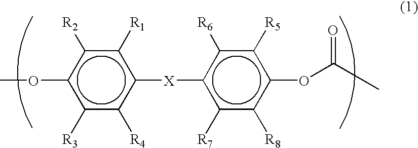
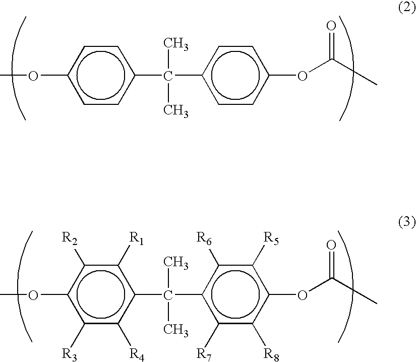
[0117]284 parts by weight of 3,3′,5,5′-tetramethylbisphenol A and 225 parts by weight of DPC were polymerized through de-phenolation, using 0.2 parts by weight of sodium salt of bisphenol A as a catalyst, in a nitrogen atmosphere at 200 to 280° C., thereby obtaining a homopolymer of 3,3′,5,5′-tetramethylbisphenol A. The limiting viscosity number of the polymer was 0.35. The polymer was dissolved in methylene chloride to prepare a 22 wt. % solution. The obtained solution was cast onto a polyester film according to a die coating process, and then dried at 100° C. for 10 minutes to thereby form a polycarbonate film having a thickness of 120 μm.

[0118]After treated at 200° C. for 10 minutes, the thermal shrinkage of the polycarbonate film in the machine direction thereof was −0.98%; and the thermal shrinkage thereof in the transverse direction was −0.97%. After treated at 230° C. for 10 minutes, the thermal shrinkage of the film in the machine direction was...


PUM


Abstract

A laminate for dye-sensitized solar cell comprising a plastic film of which the thermal shrinkage in the machine direction thereof when heat-treated at 200° C. for 10 minutes is from −1.5 to +0.5%, and a transparent conductive layer provided on the film, which comprises essentially indium oxide with zinc oxide added thereto and has a surface resistivity of at most 40 Ω / square, may give a highly-durable and flexible, dye-sensitized solar cells having high photovoltaic power generation efficiency.

Description

TECHNICAL FIELD[0001]The present invention relates to a laminate for dye-sensitized solar cells and an electrode for dye-sensitized solar cells. More precisely, the invention relates to a laminate for dye-sensitized solar cells, an electrode for dye-sensitized solar cells and a method for producing it, capable of producing highly-durable and flexible, dye-sensitized solar cells having high photovoltaic efficiency.BACKGROUND ART[0002]Since the proposal of a photoelectric conversion device that comprises dye-sensitized semiconductor particles (Nature, Vol. 353, pp. 737-740, 1991), a dye-sensitized solar cell is much noticed as a new solar cell substitutable for a silicon-based solar cell. In particular, a dye-sensitized solar cell comprising a plastic film as the support thereof is flexible and lightweight, and many investigations on it have been made.DISCLOSURE OF THE INVENTION[0003]An electrode for dye-sensitized solar cell comprises a support, a transparent conductive layer formed ...

Claims


Application Information

Patent Timeline
Patent Type & Authority Patents(United States)
IPC IPC(8): H01L31/00H01L21/00B32B27/06
CPCH01G9/2036H01G9/2095H01M14/005H01L51/442Y02E10/542Y10T428/31786Y02P70/50H10K30/82H01L31/04
Inventor KUBO, KOJINISHIO, REIHARA, HIROSHIMITZUTANI, KEI
Owner TOYOBO CO LTD
Why Eureka
Try Eureka