
Method and apparatus for polishing a substrate having a grinded back surface

a technology of substrate and back surface, which is applied in the direction of edge grinding machines, grinding machine components, manufacturing tools, etc., can solve the problems of affecting the uniform grinding affecting the uniformity of the back surface, and the substrate itself may be broken, so as to achieve the effect of uniform polishing, shortening the air cutting time, and quick application of the substra

Active Publication Date: 2013-09-17
EBARA CORP
View PDF30 Cites 5 Cited by
  • Summary
  • Abstract
  • Description
  • Claims
  • Application Information

AI Technical Summary

Benefits of technology

The flexible polishing tape reduces the risk of chipping and allows for faster polishing, shortening the air-cutting time and achieving uniform results even with protection films attached, thereby enhancing the substrate's surface quality and processing efficiency.

Problems solved by technology

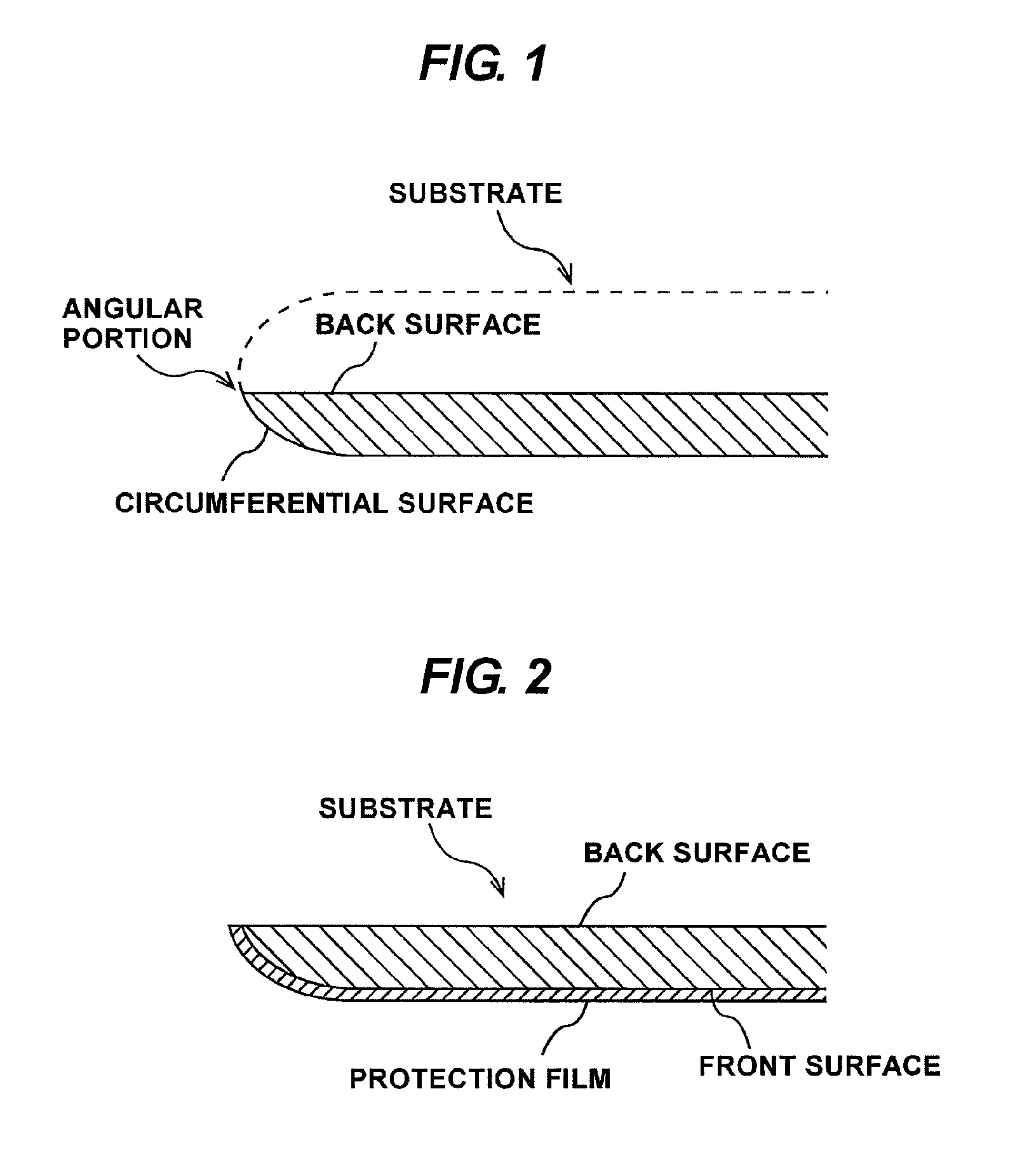
Such acute angular portion is likely to be chipped by a physical contact, and the substrate itself may be broken during transportation of the substrate.
Particularly, in the nature of the substrate, once the substrate is chipped, the crack tends to extend into a region where devices are formed, thus causing defects of products.
Further, the angular portion may hinder uniform grinding of the back surface, and may even cause cracking of the substrate during grinding.
However, the substrate is not perfectly round and moreover it is difficult to strictly align the center of the substrate with a rotational axis of the support stage.
Therefore, when the grinding stone contacts the angular portion of the substrate, the grinding stone may damage the substrate.
However, this results in a longer time for bringing the grinding stone into contact with the substrate (this time is referred to as “air-cutting time”), thus lowering throughput.
Consequently, a long grinding time is needed for softening an impact between the grinding stone, which is a rigid body, and the substrate.
However, if an adhesive, which is used for the protection film, exists unevenly in a circumferential direction of the substrate, the protection film may locally hinder polishing of the substrate.
As a result, the substrate is unevenly polished.
Further, the adhesive may be attached to the grinding stone, thus lowering the polishing performance of the grinding stone.

Method used


Image

  • Method and apparatus for polishing a substrate having a grinded back surface
  • Method and apparatus for polishing a substrate having a grinded back surface
  • Method and apparatus for polishing a substrate having a grinded back surface

Examples


Embodiment Construction

[0043]Embodiments of the present invention will be described below with reference to the drawings.

[0044]An object to be polished by a polishing method of the present invention is a thin substrate used in fabrication processes of SOI (Silicon on Insulator) substrate, through-silicon via (TSV), and power device (i.e., semiconductor element for electric power). This thin substrate has a back surface that has been grinded by a grinding tool (e.g., a back grinder). The SOI substrate is a substrate having an insulating layer of SiO2 and a silicon single crystal layer formed on the insulating layer. The through-silicon via (TSV) is an electrode extending vertically through a semiconductor chip. The power device is an element that converts electric power into another form of electric power or an element that controls electric power. Typical examples of the power device include power transistor, thyristor, and rectifier diode.

[0045]The object to be polished according to the polishing method ...


PUM

PropertyMeasurementUnit
thicknessaaaaaaaaaa
angleaaaaaaaaaa
angleaaaaaaaaaa

Abstract

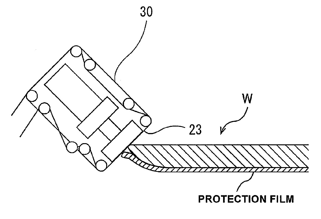
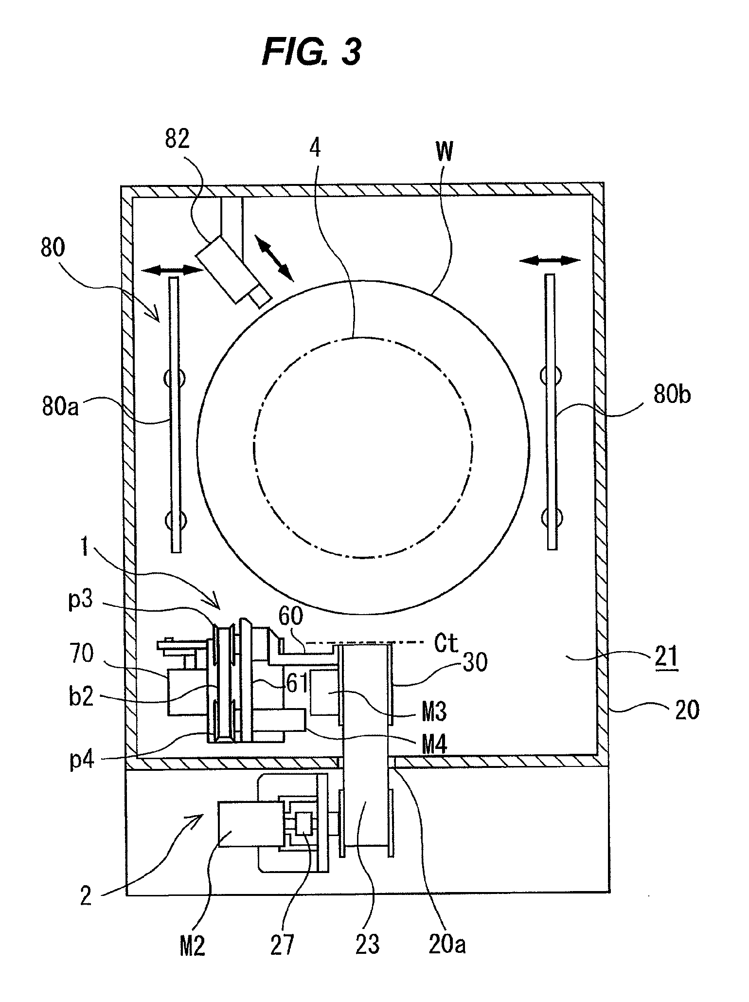
A method capable of quickly polishing an angular portion formed by a grinded back surface and a circumferential surface of a substrate without causing damages on the thin substrate is provided. The method includes rotating the substrate about its center, and pressing a polishing tape against the angular portion formed by the back surface and the circumferential surface of the substrate to polish the angular portion.

Description

BACKGROUND OF THE INVENTION[0001]1. Field of the Invention[0002]The present invention relates to a method and an apparatus for polishing a substrate after a back surface of the substrate is grinded, and more particularly to a method and an apparatus for polishing an angular portion formed by the grinded back surface and a circumferential surface of the substrate.[0003]2. Description of the Related Art[0004]In fabrication processes of SOI (Silicon on Insulator) substrate, through-silicon via (TSV), power device (i.e., semiconductor element for electric power), and the like, a back surface of a substrate is grinded for making the substrate thinner. In this grinding process, a grinding tool, which is called a back grinder, is used. The back surface of the substrate is grinded until a thickness of the substrate is reduced to, for example, 300 μm or less. Specifically, the back surface of the substrate is pressed against the rotating back grinder, so that the back surface of the substrat...

Claims


Application Information

Patent Timeline
Patent Type & Authority Patents(United States)
IPC IPC(8): B24B1/00B24B9/00B24B21/00B24B21/02H01L21/304
CPCB24B21/002B24B9/065
Inventor NAKANISHI, MASAYUKIONOZAWA, MASUNOBUSEKI, MASAYA
Owner EBARA CORP
Learn More