
Melt supply pipe for aluminum die casting

a technology of aluminum die casting and supply pipe, which is applied in the direction of heat treatment equipment, manufacturing converters, furnaces, etc., can solve the problems of large gap between the inner and outer pipes, leakage of molten aluminum alloy from the connecting portions, and weak impact resistance, so as to prevent the leakage enhance the melting loss resistance of molten aluminum alloy, and high impact resistance

Inactive Publication Date: 2012-12-18
TOSHIBA MASCH CO LTD
View PDF26 Cites 6 Cited by
  • Summary
  • Abstract
  • Description
  • Claims
  • Application Information

AI Technical Summary

Benefits of technology

[0010]It is therefore an object of the present invention to solve the above problems in the prior art and provide a melt supply pipe for aluminum die casting which is strong to mechanical impact and is excellent in the melting loss resistance to a molten aluminum alloy and which has a significantly extended life, and a method for producing the melt supply pipe.
[0017]According to the present invention, the outer steel pipe can protect the inner ceramic pipe from mechanical impact and, in addition, enables application of a sufficient clamp load on the terminal connecting portions of the melt supply pipe, thereby preventing leakage of a molten aluminum alloy. Furthermore, owing to TiC particles densely scattered over the inner circumferential surface of the outer pipe, the present melt supply pipe has significantly enhanced melting loss resistance to a molten aluminum alloy. Thus, the melting supply pipe of the present invention, having both high impact resistance and high meting loss resistance, can enjoy a significantly extended life.

Problems solved by technology

While a ceramic pipe is thus strong to a molten aluminum alloy, it is weak to impact and can be broken by its vibration during operation or by erroneous handling upon its maintenance.
Further, only an insufficient load can be applied on the connecting portions of such a breakable ceramic pipe, which could cause leakage of a molten aluminum alloy from the connecting portions.
However, because of a large difference in thermal expansion coefficient between the steel pipe and the ceramic or graphitic pipe, a large gap can be formed between the inner and outer pipes due to their different thermal expansions.
A molten aluminum alloy will easily intrude into the gap, which may result in melting loss of the steel pipe and formation of holes therein in a short period of time.

Method used


Image

  • Melt supply pipe for aluminum die casting
  • Melt supply pipe for aluminum die casting
  • Melt supply pipe for aluminum die casting

Examples


first embodiment

[0026]FIG. 1 is a cross-sectional diagram showing the structure of a melt supply pipe according to the present invention. In FIG. 1, reference numeral 10 denotes an inner ceramic pipe and reference numeral 12 denotes an outer steel pipe. The inner pipe 10 / outer pipe 12 integral structure of the melt supply pipe is obtained by fitting the outer pipe 12 to the inner pipe 10.

[0027]As shown in FIG. 2 which is an enlarged view of the portion A of FIG. 1, the entire inner circumferential surface of the outer steel pipe 12 is coated with a Ni alloy layer 13, and the surface of the Ni alloy layer 13 is covered with a myriad of titanium carbide (TiC) particles. The TiC particles 14 are bonded in a particulate state to the Ni alloy layer 13 such that they partly protrude from the surface of the Ni alloy layer 13. Preferably, the gaps in the TiC particles are filled in with fine ceramic particles 15 comprising at least one of boron nitride (BN), alumina (Al2O3), zirconia (ZrO2) and silicon nit...

second embodiment

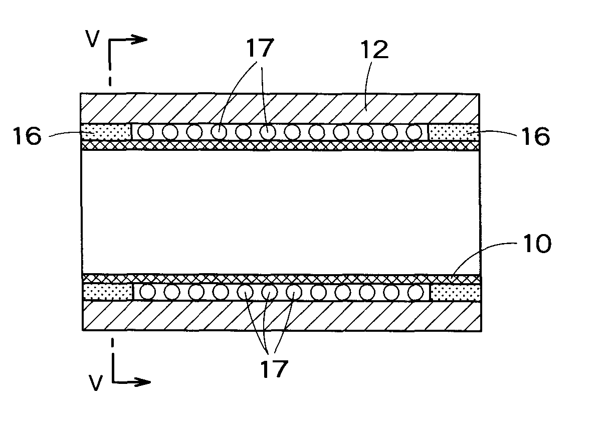
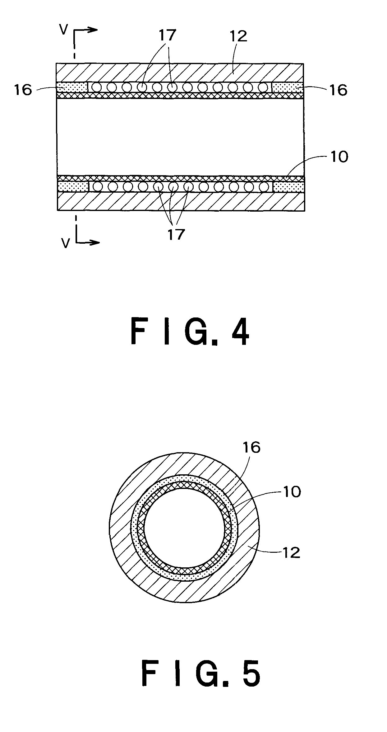
[0033]A melt supply pipe for aluminum die casting according to the present invention will now be described with reference to FIGS. 4 and 5.

[0034]In the melt supply pipe of the second embodiment, a pair of fire-resistant sheets 16 is sandwiched between the inner ceramic pipe 10 and the outer steel pipe 12 at both ends of the pipes, and the gap formed between the inner and outer pipes and defined by the fire-resistant sheets 16 is filled with ceramic balls 17.

[0035]The fire-resistant sheet 16 is a sheet member composed of inorganic fibers having the property of expanding by heating. Preferably, each fire-resistant sheet 16 extends over the entire circumference, and the outer end of the sheet is aligned with the end surfaces of the inner pipe 10 and the outer pipe 12. The balls 17 are a spherical filler formed of a ceramic material comprising at least one of Al2O3, SiC, Si3N4, MgO, Al2TiO5, ZrO2, and sialon. It is also possible to use a particulate filler instead of the balls 17.

[0036]...


PUM

PropertyMeasurementUnit
average particle diameteraaaaaaaaaa
diameteraaaaaaaaaa
particle diameteraaaaaaaaaa

Abstract

There is provided a melt supply pipe for aluminum die casting which is strong to mechanical impact and is excellent in the melting loss resistance to a molten aluminum alloy and which has a significantly extended life. The melt supply pipe for connecting a melting furnace and a plunger sleeve of a die casting machine, includes an inner ceramic pipe and an outer steel pipe fitted to the inner pipe, wherein a Ni alloy layer is formed over the inner circumferential surface of the outer steel pipe, and TiC particles are bonded to the surface of the Ni alloy layer.

Description

BACKGROUND OF THE INVENTION[0001]1. Field of the Invention[0002]The present invention relates to a melt supply pipe for supplying a molten aluminum alloy from a melting furnace to a plunger sleeve of a die casting machine in aluminum die casting.[0003]2. Background Art[0004]In conventional die casting machines, a ladle method has been commonly employed for supplying a molten aluminum alloy to a plunger sleeve. According to the ladle method, a molten aluminum alloy is drawn from a melting furnace by means of a ladle and supplied to a plunger sleeve.[0005]As a technique to take the place of the ladle method, a melt supply pipe method has recently been attracting attention which involves directly connecting a melting furnace and a plunger sleeve with a melt supply pipe, and supplying a molten aluminum alloy through the melt supply pipe to the plunger sleeve. Mixing of an Al oxide film or solid broken pieces into a molten aluminum alloy can be significantly reduced with the melt supply ...

Claims


Application Information

Patent Timeline
Patent Type & Authority Patents(United States)
IPC IPC(8): C21D8/10
CPCC21D8/10B23P17/00Y10T29/49885B22D11/003B22D17/04B22D17/30C22C21/00
Inventor MASUDA, JUNFUJIMOTO, RYOSUKE
Owner TOSHIBA MASCH CO LTD
Learn More