
Foreign substance inspection apparatus, exposure apparatus, and method of manufacturing device

a technology of exposure apparatus and foreign substance, applied in the direction of instruments, originals for photomechanical treatment, material analysis by optical means, etc., can solve the problems of reducing the lowering the manufacturing yield of the device, and unable to obtain the exact particle size of the foreign substan

Inactive Publication Date: 2012-12-11
CANON KK
View PDF8 Cites 0 Cited by
  • Summary
  • Abstract
  • Description
  • Claims
  • Application Information

AI Technical Summary

Benefits of technology

The present invention is a foreign substance inspection apparatus that can accurately determine the particle sizes of foreign substances on a surface. It uses a light projecting unit to illuminate the surface, a detector to collect the scattered light, and a processing unit to analyze the intensity of the light and determine the particle size of any foreign substances present. The apparatus can determine the particle size based on the intensity of the scattered light and the position on the surface where it is detected. This allows for precise inspection of foreign substances on a surface.

Problems solved by technology

During this transfer, if a pattern defect or a foreign substance such as dirt is present on the reticle, the pattern defect or the foreign substance is transferred onto the wafer, together with the circuit pattern, which lowers the device manufacturing yield.
Especially when a large number of circuit patterns are repeatedly printed on a wafer by the step & repeat method using a reticle, one harmful foreign substance, if any, on the reticle is printed on the entire wafer, and this considerably lowers the device yield.
However, the conventional inspection apparatus uses a table or curve common to the entire region on an inspection surface based on histograms, so it can obtain only one average conversion table or conversion curve for each inspection surface.
Thus, unless the intensity of scattered light and the particle size of a foreign substance, detected by the inspection apparatus, have a uniform relationship within the plane of the inspection surface, the exact particle size of the foreign substance cannot be obtained.

Method used


Image

  • Foreign substance inspection apparatus, exposure apparatus, and method of manufacturing device
  • Foreign substance inspection apparatus, exposure apparatus, and method of manufacturing device
  • Foreign substance inspection apparatus, exposure apparatus, and method of manufacturing device

Examples


first embodiment

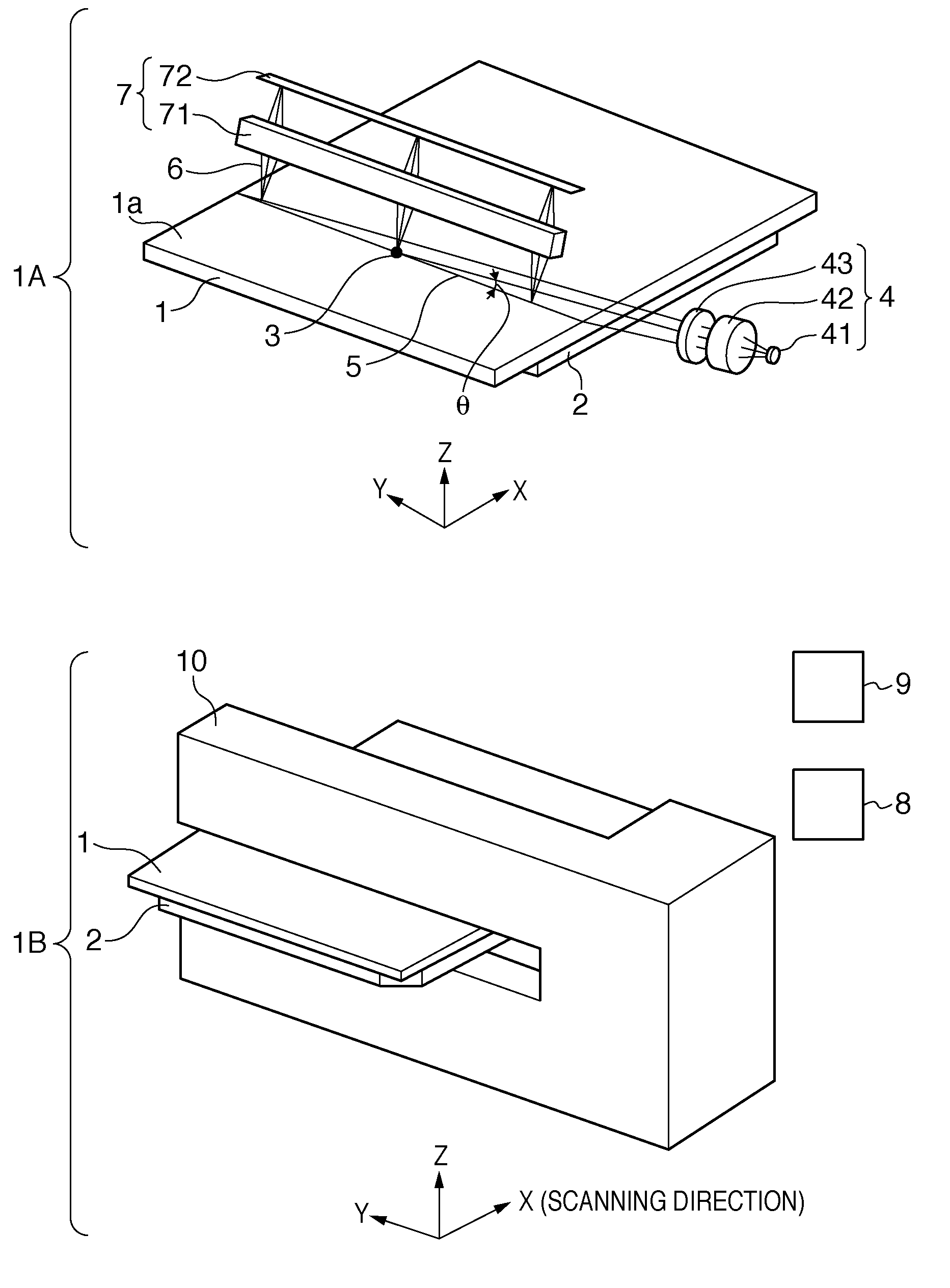
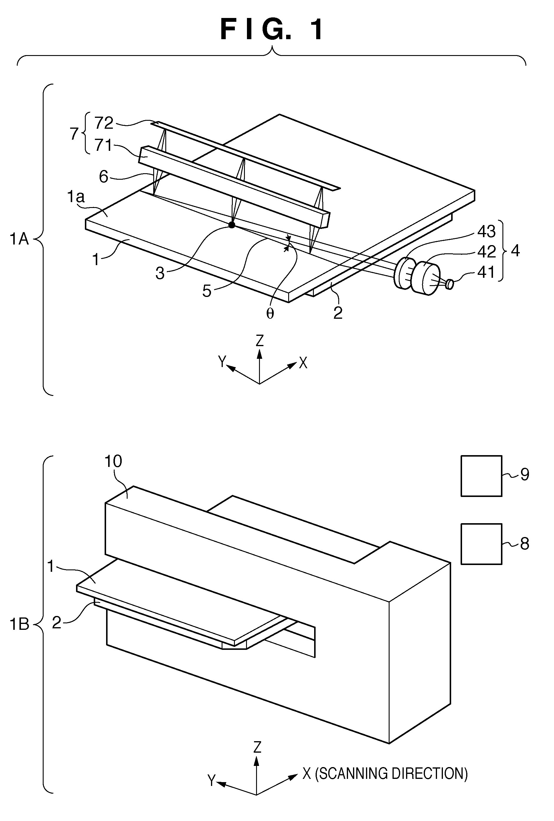
[0023]A method of determining the particle size of a foreign substance by an inspection apparatus will be described with reference to 4A to 4D in FIGS. 4 and 5. 4A and 4B in FIG. 4 illustrate an example of the regions where foreign substances are detected by inspection, and conversion curves. The relationship between the intensity of scattered light detected by a line sensor 72 and the particle size of a foreign substance differs depending on the two-dimensional coordinate position on an inspection surface. In the first embodiment, the inspection surface is divided into four regions: regions 81 to 84, and a processing unit 8 of the inspection apparatus holds a plurality of conversion curves 91 to 94 corresponding to the plurality of regions 81 to 84, respectively. 4C and 4D in FIG. 4 are views for explaining a method of calculating the particle size of a foreign substance by selecting a conversion curve in the region to which the two-dimensional coordinate position of the detected f...

second embodiment

[0026]The second embodiment will be described with reference to FIGS. 5 and 6A to 6C in FIG. 6. In the second embodiment, the inspection surface is divided into, for example, 16 regions, as shown in 6A in FIG. 6. A processing unit 8 of an inspection apparatus stores conversion curves 95, 96, 97, and 98 corresponding to four regions 85, 86, 87, and 88, respectively, as shown in 6B in FIG. 6. However, the processing unit 8 holds no conversion curves in regions other than the four regions 85 to 88. In step S1, the inspection apparatus inspects the inspection surface for foreign substances. In step S2, a detector 7 obtains the positions of the foreign substances adhering on the inspection surface, and their detection voltages. In step S3, the processing unit 8 of the inspection apparatus selects or calculates conversion curves used to determine the particle sizes of the foreign substances. The processing unit 8 selects the conversion curves 95 to 98 corresponding to the regions 85 to 88...

third embodiment

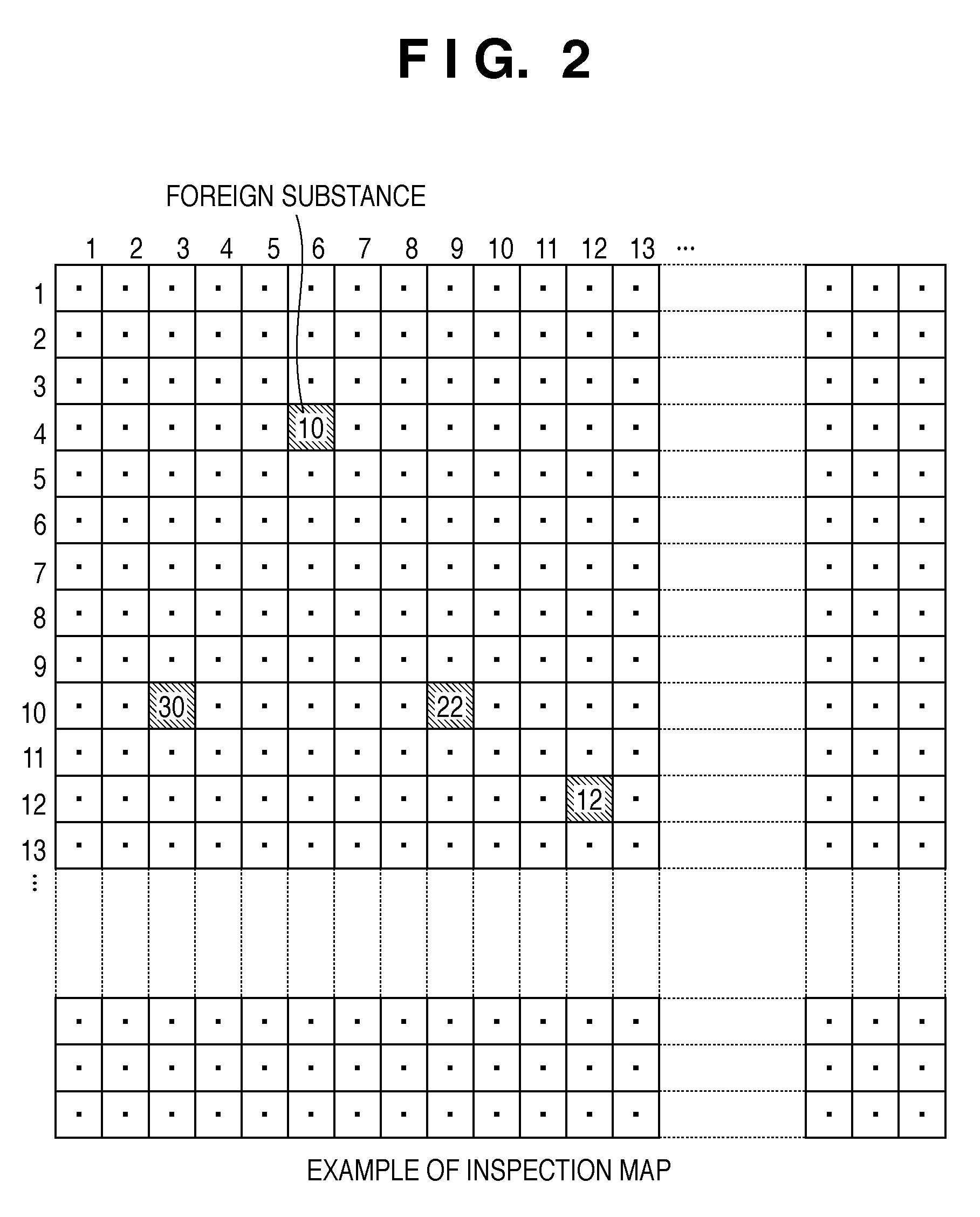
[0030]An embodiment in which conversion curves are generated will be described with reference to FIGS. 7 and 8A to 8C in FIG. 8. FIG. 7 illustrates an example of the sequence of a process of generating conversion curves by an inspection apparatus. 8A to 8C in FIG. 8 illustrate an example of foreign substance information and conversion curves referred to in an explanation of the process sequence. The inspection apparatus sets a coordinate position for each 1×1-mm grid defined on the inspection surface, as shown in the inspection map of FIG. 2. Although a coordinate position is set for each 1×1-mm grid in the third embodiment, the grid size can be changed in accordance with the number of division of the area of the inspection region. The inspection apparatus holds a storage area for grid-specific conversion curves. In step S11, a test reticle is loaded into the inspection apparatus. The test reticle is coated with foreign substances with specific particle sizes at specific coordinate ...


PUM

PropertyMeasurementUnit
sizesaaaaaaaaaa
sizesaaaaaaaaaa
sizesaaaaaaaaaa

Abstract

A foreign substance inspection apparatus includes a light projecting unit, a detector which detects the intensity of scattered light of light projected onto the surface of an object to be detected by the light projecting unit, in association with the two-dimensional coordinate position on the surface, and a processing unit. The relationship between the intensity of the scattered light detected by the detector and the particle size of the foreign substance differs depending on the two-dimensional coordinate position on the surface. The processing unit determines, a conversion curve to convert the intensity of the scattered light detected by the detector into the particle size of the foreign substance, in accordance with the two-dimensional coordinate position of the foreign substance detected by the detector, and converts the intensity of the scattered light detected by the detector into the particle size of the foreign substance using the determined conversion curve.

Description

BACKGROUND OF THE INVENTION[0001]1. Field of the Invention[0002]The present invention relates to a foreign substance inspection apparatus, which efficiently detects foreign substances on a reticle called a photomask or on a protective film called a pellicle, an exposure apparatus having the inspection apparatus, and a method of manufacturing a device. The reticle has a circuit pattern formed on it, which is used to manufacture a device, for example, a semiconductor device such as an integrated circuit or a large-scale integration, a charge-coupled device, a liquid crystal panel, or a magnetic head. The pellicle is a protective cover attached to the reticle in order to prevent any foreign substances from adhering onto the reticle.[0003]2. Description of the Related Art[0004]In the process of manufacturing a device, an exposure apparatus (a stepper or a mask aligner) generally transfers a circuit pattern formed on a reticle onto a wafer coated with a resist. During this transfer, if a...

Claims


Application Information

Patent Timeline
Patent Type & Authority Patents(United States)
IPC IPC(8): G01N21/00G01N15/02G01N21/956G03F1/84
CPCG01N21/94G01N2021/945G01N2021/95676
Inventor KAWAHARA, ATSUSHI
Owner CANON KK
Learn More