
A Particle Size Detection Method Based on Optical Trapping

A particle size and detection method technology, which is applied in particle and sedimentation analysis, measuring devices, particle size analysis, etc., can solve the problems of difficulty in ensuring experimental accuracy, influence of particle radius, error, etc., and achieve the effect of easy application

Active Publication Date: 2017-02-22
UNIV OF SCI & TECH OF CHINA
View PDF3 Cites 0 Cited by
  • Summary
  • Abstract
  • Description
  • Claims
  • Application Information

AI Technical Summary

Problems solved by technology

Even if the microscopic image edge detection method is used, due to the influence of illumination, axial position and operator, there is a large error between the measured particle size and the real value, so the accuracy of the experiment is difficult to guarantee
[0004] Based on the optical tweezers system with a high-precision fast position detector, the present invention proposes a set of standard operating procedures and data analysis methods to accurately measure the particle size and solve the problem of being affected by the particle radius in the measurement of single-molecule force spectrum

Method used


Image

  • A Particle Size Detection Method Based on Optical Trapping
  • A Particle Size Detection Method Based on Optical Trapping
  • A Particle Size Detection Method Based on Optical Trapping

Examples


Embodiment Construction

[0025] The present invention will be described in detail below in conjunction with the accompanying drawings and specific embodiments, but the scope of protection of the present invention is not limited to the following examples, but should include all content in the claims.

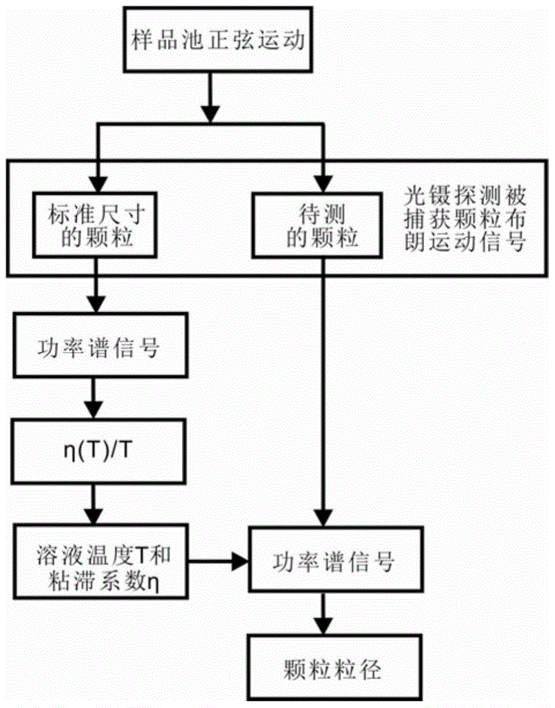
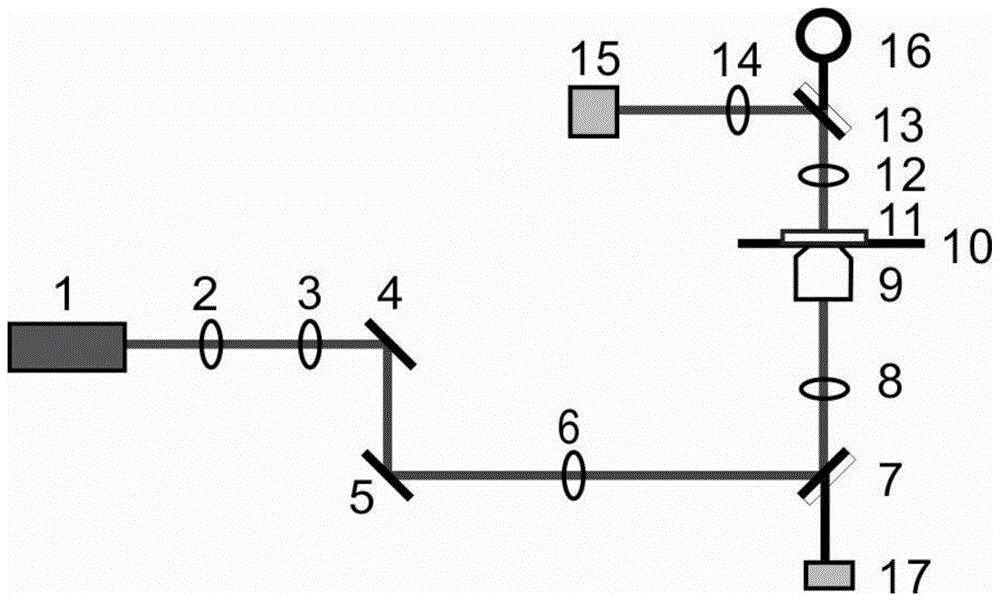
[0026] The detection process of the present invention is shown in figure 1 , using the power spectrum signal of standard size particles to measure the temperature and viscosity coefficient of the solution, and then use the measured parameters to detect the size of the particles to be tested. The experimental detection basis of the present invention needs to have a set of optical tweezers system with photoelectric detection, see figure 2 . The laser beam expands through lenses 2 and 3 and enters a pair of mirrors 4 and 5 in parallel, and then expands through lenses 6 and 8 to a spot of about 6mm in the rear pupil of the objective lens 9. The 45-degree semi-reflective and semi-transparent plane mirror 7...


PUM

PropertyMeasurementUnit
diameteraaaaaaaaaa

Abstract

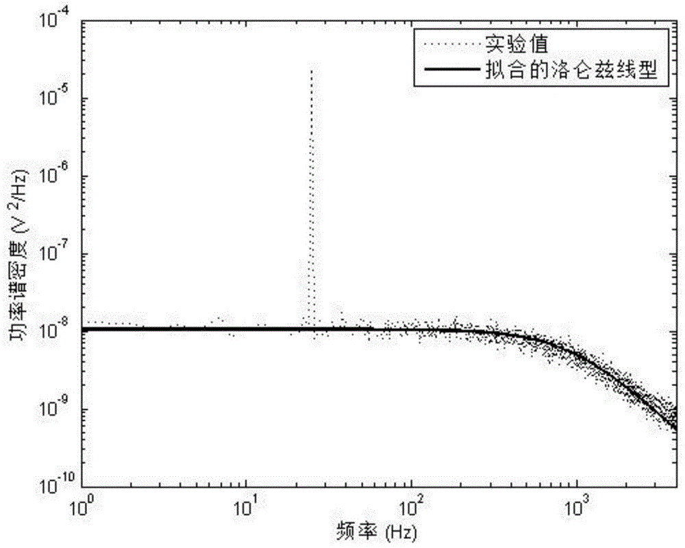
The invention provides a particle diameter detection method based on optical trapping. The method comprises the following steps of analyzing the power spectrum of displacement of particles trapped by an optical trap, wherein a signal comprises Lorentz distribution corresponding to limited Brownian movement and peak of forced movement; according to the area of the peak relative to the Lorentz distribution and the height of the peak, inverting the voltage proportion coefficient of a micro particle in the optical trap when the micro particle is detected by a detector, and according to the micro particle diameter with the standard size, measuring the ratio of coefficient of viscosity to temperature; acquiring the temperature in the optical trap according to the relationship between the coefficient of viscosity and the temperature; collecting a forced movement signal of a to-be-detected micro particle in the optical trap, and then calibrating the voltage proportion coefficient of the detector to the micro particle by utilizing the power spectrum; and acquiring the diffusion coefficient by the power spectrum of thermal noise, and determining the particle radius according to the temperature, the coefficient of viscosity as well as Stokes-Einstein relation of standard micro particle measurement. The method can be used for detecting the particle diameter of each particle in an experiment environment, that is, the method can be used for detecting the particle diameter with high precision in situ.

Description

technical field [0001] The invention belongs to the technical fields of particle diameter detection, single molecule measurement method and optical micro-manipulation, and in particular relates to a particle diameter detection method based on optical trapping. Background technique [0002] Particle size detection is widely used in many fields, such as particle size measurement in various powder industries, particle size measurement in suspension liquid medicine, and cell size measurement. At present, there are many technical methods widely used to measure particle size in large quantities, such as sieve analysis method, sedimentation balance method, electrical resistance method and laser scattering method. [0003] In the study of the mechanical properties of biological macromolecules, when optical tweezers or other measurement tools are used, the characteristic is that the purpose of detecting the mechanical properties of single molecules is achieved by coupling macromolecu...

Claims


Application Information

Patent Timeline
Patent Type & Authority Patents(China)
IPC IPC(8): G01N15/02
Inventor 周金华李迪李银妹钟敏成王自强
Owner UNIV OF SCI & TECH OF CHINA
Learn More