
Hybrid magnetic-based and impedance-based position sensing

a technology of impedance-based sensing and hybrid magnetic based, which is applied in the field of sensing the position, can solve the problems of inaccuracy of impedance-based position sensing and magnetic-based methods, and achieve the effect of low cost and high accuracy of magnetic position sensing

Active Publication Date: 2007-01-18
BIOSENSE WEBSTER INC
View PDF19 Cites 336 Cited by
  • Summary
  • Abstract
  • Description
  • Claims
  • Application Information

AI Technical Summary

Benefits of technology

The present invention provides a hybrid position sensing system that combines magnetic and electrical sensing techniques. This system utilizes a magnetic field transducer and electrodes to accurately position a probe in a body cavity. The magnetic field transducer provides accurate position coordinates, while the electrical impedance sensors measure the position of the probe relative to the body surface. This allows for the calibration of the electrical impedance sensors with the magnetic position measurements, resulting in the accurate positioning of the probe. The hybrid probe can also be used to calibrate additional catheters introduced into the body cavity simultaneously or afterward. The system provides a reliable and accurate means for position sensing in the body cavity, which can aid in the performance of medical procedures.

Problems solved by technology

However, due in part to the non-linear impedance of the body, impedance-based position sensing is not as accurate as magnetic-based methods.

Method used


Image

  • Hybrid magnetic-based and impedance-based position sensing
  • Hybrid magnetic-based and impedance-based position sensing
  • Hybrid magnetic-based and impedance-based position sensing

Examples


Embodiment Construction

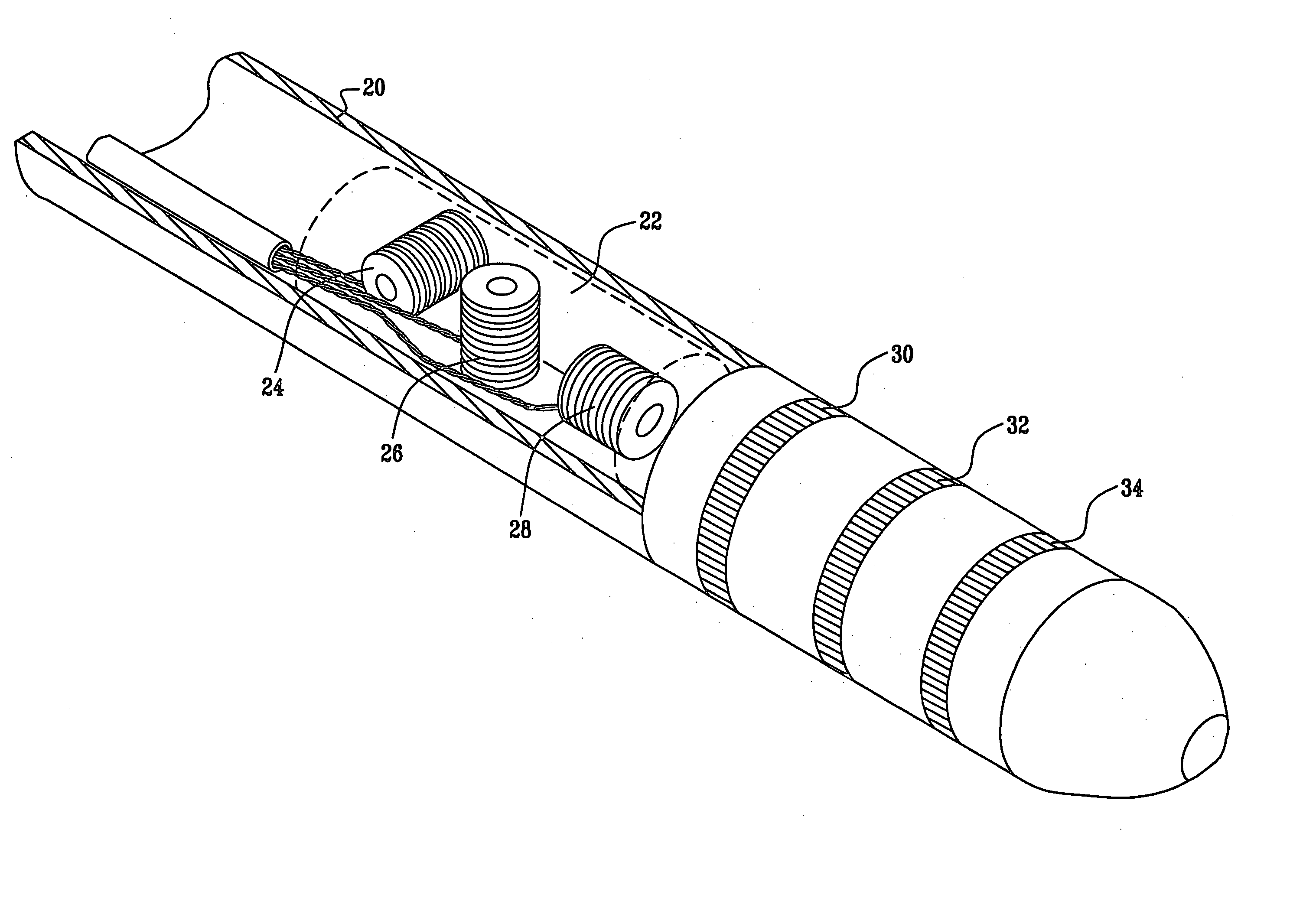
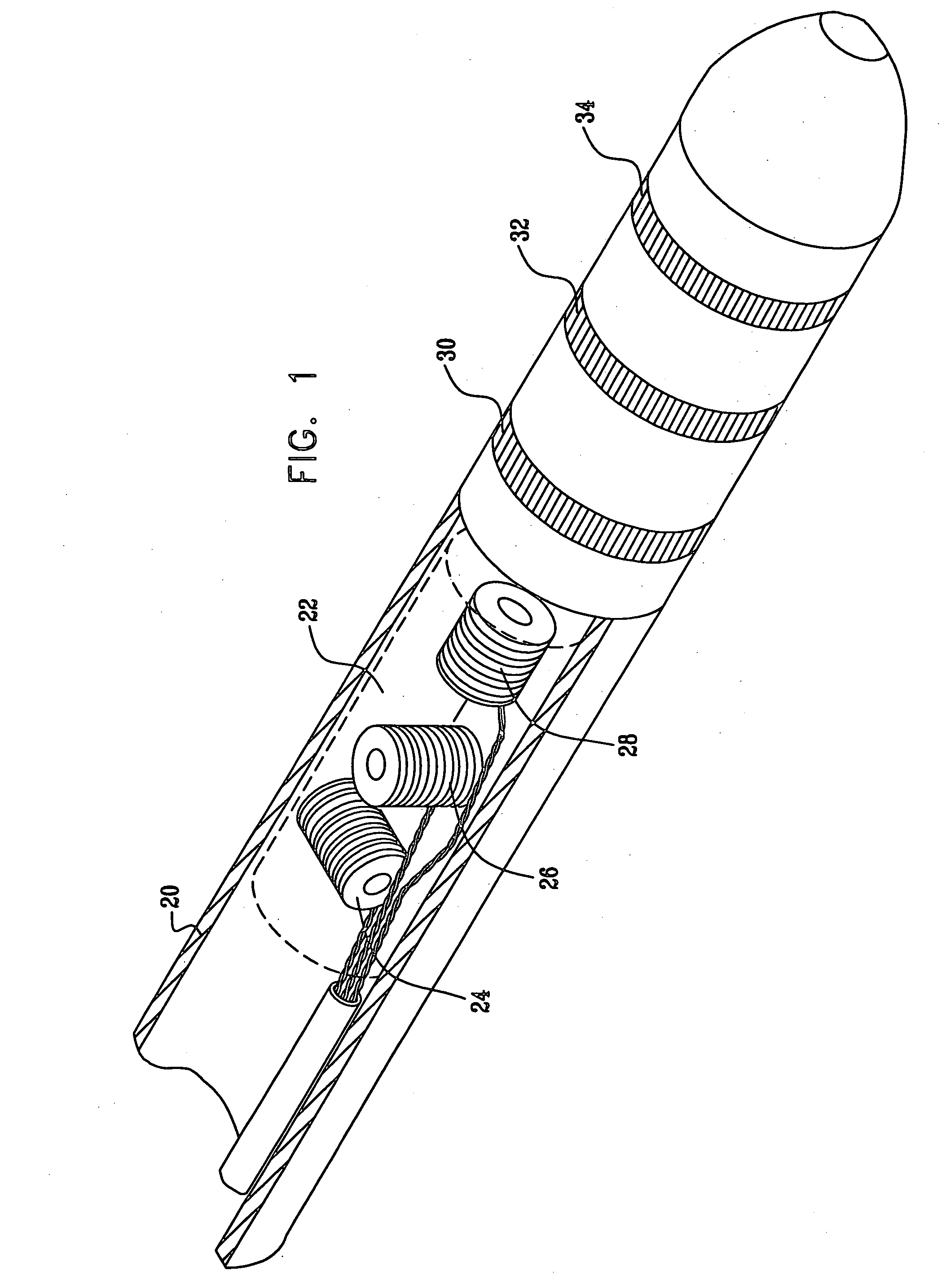
[0043]FIG. 1 is a schematic detail view showing the distal end of a hybrid catheter 20, comprising a magnetic field position sensor 22 and multiple catheter electrodes 30, 32, and 34, in accordance with an embodiment of the present invention.

[0044] Magnetic field sensor 22 comprises three orthogonal coils 24, 26, and 28, which may be used to determine the coordinates of catheter 20 in six position and orientation dimensions, as described in the patents cited in the Background of the Invention. Alternatively, magnetic field sensor 22 may comprise one or two coils or a greater number of coils, or magnetic field sensors other than coils, such as Hall effect devices or other antennae. In the context of the present patent application and in the claims, such coils and other sensors are referred to generically as magnetic field transducers, and may generally be used either to sense magnetic fields or to generate magnetic fields.

[0045] Electrodes 30, 32, and 34 may be of any suitable shap...


PUM


Abstract

A position sensing system includes a probe adapted to be introduced into a body cavity of a subject. The probe includes a magnetic field transducer and at least one probe electrodes. A control unit is configured to measure position coordinates of the probe using the magnetic field transducer. The control unit also measures an impedance between the at least one probe electrodes and one or more points on a body surface of the subject. Using the measured position coordinates, the control unit calibrates the measured impedance.

Description

FIELD OF THE INVENTION [0001] The present invention relates generally to sensing the position of an object placed within a living body, and specifically to providing an accurate reference for impedance-based position sensors. BACKGROUND OF THE INVENTION [0002] Tracking the position of intrabody objects, such as sensors, tubes, catheters, dispensing devices, and implants, is required for many medical procedures. Well-established, highly accurate systems for determining the position of an intrabody object have been developed based on magnetic field sensing. These systems utilize sensors affixed to the intrabody object to measure the relative strengths of externally-generated magnetic fields and to derive from these measurements the position of the object. Methods for magnetic-based position sensing are disclosed, for example, in U.S. Pat. Nos. 5,391,199, 5,443,489, and 6,788,967 to Ben-Haim, in U.S. Pat. No. 6,690,963 to Ben-Haim, et al., in U.S. Pat. No. 5,558,091 to Acker et al., in...

Claims


Application Information

Patent Timeline
Patent Type & Authority Applications(United States)
IPC IPC(8): A61B5/05
CPCA61B5/063A61B5/0538A61B5/0035A61B5/1473A61B5/00
Inventor GOVARI, ASSAFALTMANN, ANDRES CLAUDIOSCHWARTZ, YITZHACK
Owner BIOSENSE WEBSTER INC
Learn More