
Microparticle counting system using laser imaging and projection

A technology of tiny particles and laser imaging, applied in the field of counting system, it can solve the problems of projection distortion, voltage instability, reduce calculation, etc., to achieve the effect of reliable data science, avoid errors, accurate counting and particle size

Inactive Publication Date: 2016-06-22
新乡天翼过滤技术检测有限公司
View PDF10 Cites 0 Cited by
  • Summary
  • Abstract
  • Description
  • Claims
  • Application Information

AI Technical Summary

Problems solved by technology

[0002] At present, the known laser particle counting system uses a single laser projection, and uses the voltage pulse generated by the shadow projected on the opposite side to calculate the particle size and count. For tiny particles, scattering is easy to occur, and the generated voltage is also unstable. In laser projection, many particles with overlapping projections will be counted down, and some particles that are connected by projections will also be enlarged in particle size. The original laser counting system uses a static laser, and the medium carrying tiny particles is flowing. , resulting in projection distortion and other phenomena

Method used


Image

  • Microparticle counting system using laser imaging and projection

Examples


Embodiment Construction

[0008] In order to make the object, technical solution and advantages of the present invention clearer, the present invention will be further described in detail below in conjunction with the accompanying drawings.

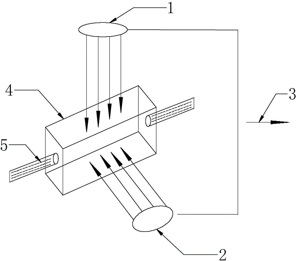
[0009] The embodiment of the present invention uses laser imaging and projection micro particle counting system, including a first laser source 1 irradiated along the X-axis direction and a second laser source 2 irradiated along the Y-axis direction, the first laser source 1 and the second laser The source 2 is respectively connected with the circuit board and the chip 3 in the counting device, and also includes a regular channel 4 along the Z-axis direction. A tiny particle medium 5 is arranged in the regular channel 4. The speed of the measured medium is within a certain range. The laser test head The fixed or laser test head moves at the same speed as the measured medium, is relatively stationary, and keeps the same speed. The current reflected on the correspond...


PUM


Abstract

The embodiment of the present invention discloses a system for counting tiny particles using laser imaging and projection. Two laser test heads on the X-axis and Y-axis are used to fix or move along the Z-axis at the same speed as the medium. The laser and particles are relatively stationary, avoiding Motion brings errors; the projections on the X-axis and the projections on the Y-axis will overlap and superimpose, and the projections on the Y-axis will also overlap and superimpose on the X-axis, and the dual laser head test is used After the head, you can use the software to analyze and calculate the position of these particles, remove the errors caused by overlapping particles and superimposed particles, and make the counting and particle size more accurate. The speed of the measured medium is within a certain range. The laser test head is fixed or laser test The head moves at the same speed as the measured medium, and is relatively stationary. The high-magnification stereoscopic imaging in two directions provides further verification and analysis for scattering, overlapping and superposition, making the data more scientific and credible.

Description

technical field [0001] The invention relates to the field of counting systems, in particular to a system for counting tiny particles using laser imaging and projection. Background technique [0002] At present, the known laser particle counting system uses a single laser projection, and uses the voltage pulse generated by the shadow projected on the opposite side to calculate the particle size and count. For tiny particles, scattering is easy to occur, and the generated voltage is also unstable. In laser projection, many particles with overlapping projections will be counted down, and some particles that are connected by projections will also be enlarged in particle size. The original laser counting system uses a static laser, and the medium carrying tiny particles is flowing. , resulting in projection distortion and other phenomena. Contents of the invention [0003] The technical problem to be solved by the embodiments of the present invention is to provide a micro part...

Claims


Application Information

Patent Timeline
Patent Type & Authority Applications(China)
IPC IPC(8): G01N15/10G01N15/02
Inventor 杨杰李正江郭文桢王可超
Owner 新乡天翼过滤技术检测有限公司
Learn More