
Thin film transistor array panel

a transistor array and thin film technology, applied in the direction of electrical equipment, semiconductor devices, instruments, etc., can solve the problems of misalignment of signal input pad and signal output pad of flexible film, change in flexible substrate size, etc., to improve junction margin and reduce process failure

Inactive Publication Date: 2011-11-15
SAMSUNG DISPLAY CO LTD
View PDF4 Cites 2 Cited by
  • Summary
  • Abstract
  • Description
  • Claims
  • Application Information

AI Technical Summary

Benefits of technology

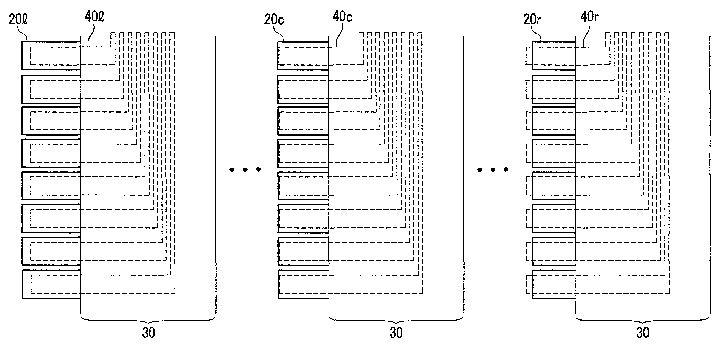
The present invention provides a thin film transistor array panel that can reduce process failures by improving the junction margin with an external driving IC even if there is a size change in the substrate during manufacturing. This is achieved by aligning the signal input pads with the driving pads on the flexible film in a pad block region, and forming the signal lines in a second direction perpendicular to the first direction in the display area. The signal input pads can be sequentially arranged and at a predetermined interval in the first direction within a pad block region, and the length of the pad block region in the first direction is longer than the length in the second direction. The flexible film can be attached to the peripheral area of the display panel and the driving pads on the flexible film can be electrically connected to the signal input pad in a pad block region. This allows for a more robust and flexible thin film transistor array panel.

Problems solved by technology

However, because a glass substrate is heavy and brittle, it is inappropriate to use the glass substrate in a display device that has a light weight, that endures some deformation, and that requires that it does not break on impact.
However, unlike a conventional glass substrate, the size of the flexible substrate may change because a flexible substrate such as a plastic substrate expands or contracts according to a manufacturing environment.
Particularly, in a process of bonding a flexible film in which a driving IC is mounted to a signal input pad of the plastic substrate, there is a problem in that the signal input pad and a signal pad of the flexible film are misaligned due to expansion or contraction of the substrate.

Method used


Image

  • Thin film transistor array panel
  • Thin film transistor array panel
  • Thin film transistor array panel

Examples


Embodiment Construction

[0038]An exemplary embodiment of the present invention will be described hereinafter in detail with reference to the accompanying drawings.

[0039]In the drawings, the thickness of layers, films, panels, regions, etc., are exaggerated for clarity. Like reference numerals designate like elements throughout the specification. When it is said that any part, such as a layer, film, area, or plate, is positioned on another part, it means the part may be directly on the other part or above the other part with at least one intermediate part. In contrast, when an element is referred to as being “directly on” another element, there are no intervening elements present.

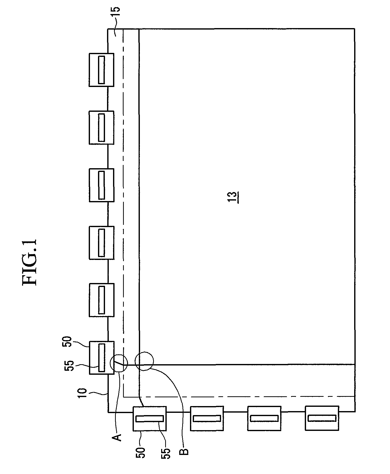
[0040]FIG. 1 is a schematic diagram of a display device according to an exemplary embodiment of the present invention.

[0041]Referring to FIG. 1, the display device includes a thin film transistor array panel 10 and a plurality of tape-carrier packages (TCP) 50.

[0042]The thin film transistor array panel 10 is partitioned into a disp...


PUM


Abstract

A thin film transistor array panel is provided according to one or more embodiments. In an embodiment, the thin film transistor array panel includes: a base substrate that has a display area and a peripheral area; a plurality of thin film transistors that are formed in the display area; a plurality of signal input pads that are formed in the peripheral area and that are formed long in a first direction; and a plurality of signal lines that are connected to the thin film transistors and the signal input pads, wherein at least a part of each of the plurality of signal input pads is arranged in a line along the first direction.

Description

CROSS-REFERENCE TO RELATED APPLICATION[0001]This application claims priority to and the benefit of Korean Patent Application No. 10-2008-0015419 filed in the Korean Intellectual Property Office on Feb. 20, 2008, the entire contents of which are incorporated herein by reference.BACKGROUND[0002](a) Technical Field[0003]Embodiments of the present invention generally relate to a thin film transistor array panel.[0004](b) Description of the Related Art[0005]In a thin film transistor array panel that is used in a general display device, a plurality of gate lines and a plurality of data lines are formed to intersect each other, a pixel electrode and a thin film transistor, which is a switching element, are formed in an intersecting region of the gate line and the data line, and signal input pads that are electrically connected to a driving device are formed at one end of each of the gate line and the data line. The driving device is mounted in a flexible circuit layer in an integrated circ...

Claims


Application Information

Patent Timeline
Patent Type & Authority Patents(United States)
IPC IPC(8): H01L27/14
CPCH01L27/124H01L29/78603G02F1/13458G02F1/136286H01L27/1214
Inventor LEE, SON-UKKIM, SUNG-JIMLEE, JEONG-KUK
Owner SAMSUNG DISPLAY CO LTD
Learn More