Processing method of workpiece
a processing method and workpiece technology, applied in the field of workpiece processing methods, can solve problems such as unstable state of laser oscillator, and achieve the effect of suppressing the laser beam to the laser oscillator and reducing the possibility of laser processing processing failur
- Summary
- Abstract
- Description
- Claims
- Application Information
AI Technical Summary
Benefits of technology
Problems solved by technology
Method used
Image
Examples
first modification example
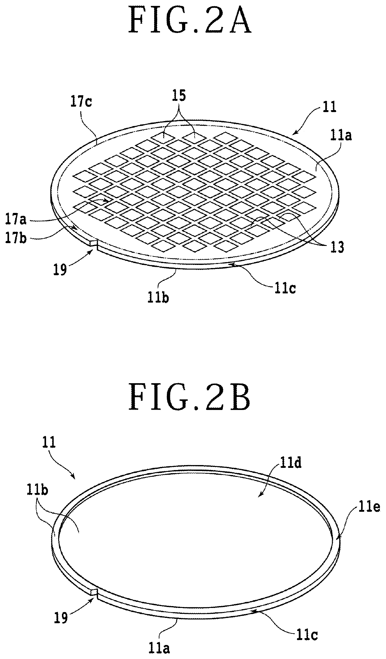
[0063]Next, various modification examples in the first embodiment will be described. FIG. 9A is a perspective view of a workpiece 31 according to a first modification example. FIG. 9B is a sectional view of the workpiece 31 according to the first modification example. The workpiece 31 of the first modification example is different from the above-described workpiece 11 in that the circular recess part 11d is not formed on the side of the back surface lib. By executing the steps from the tape sticking step S10 to the removal step S40 similarly for the workpiece 31, a region including a beveled part formed at the outer circumferential edge of the workpiece 31 can be removed.
second modification example
[0064]FIG. 10 is a perspective view of a workpiece 41 according to a second modification example. The devices 15 are not formed in the workpiece 41. For example, a workpiece 43 with a smaller diameter than the workpiece 41 can be formed from the workpiece 41 by forming the processing groove 11g along a predetermined circle having a diameter smaller than the diameter of the workpiece 41.
third modification example
[0065]Next, a modification example of the laser beam irradiation step S30 will be described. FIG. 11 is a diagram illustrating the laser beam irradiation step S30 according to a third modification example. FIG. 12 is a schematic diagram of FIG. 11. In the laser beam irradiation step S30 according to the third modification example, a state is made in which a plane 26 of incidence of the laser beam L is set parallel to a virtual plane 24 that passes through the center A1 of the front surface 11a and the focal point A2 of the laser beam L and is orthogonal to the front surface 11a. Moreover, the orientation of the laser beam L is adjusted in such a manner that the laser beam L has an angle β of incidence (acute angle) formed due to inclination with respect to the normal 11f to the front surface 11a by a predetermined angle, and the focal point A2 is positioned to one point on the boundary part 17c (annular region).
[0066]In this state, by rotating the chuck table 4 around the rotation a...
PUM
| Property | Measurement | Unit |
|---|---|---|
| thickness | aaaaa | aaaaa |
| diameter | aaaaa | aaaaa |
| diameter | aaaaa | aaaaa |
Abstract
Description
Claims
Application Information
 - R&D
- Intellectual Property
- Life Sciences
- Materials
- Tech Scout
- Unparalleled Data Quality
- Higher Quality Content
- 60% Fewer Hallucinations
Browse by: Latest US Patents, China's latest patents, Technical Efficacy Thesaurus, Application Domain, Technology Topic, Popular Technical Reports.
© 2025 PatSnap. All rights reserved.Legal|Privacy policy|Modern Slavery Act Transparency Statement|Sitemap|About US| Contact US: help@patsnap.com


