Operational control method in machine tool

a technology of operation control and machine tool, applied in the direction of computer control, program control, instruments, etc., can solve the problem that the workpiece cannot be reprocessed, and achieve the effect of improving processing efficiency, reducing labor and recovery time, and small effect on processing

Active Publication Date: 2021-02-09
OKUMA CORP
View PDF18 Cites 0 Cited by
  • Summary
  • Abstract
  • Description
  • Claims
  • Application Information

AI Technical Summary

Benefits of technology

[0014]With the embodiment, it is determined whether the simultaneous processing in which at least two or more of the tool holders perform the processings to the identical workpiece is being performed or not and whether the cutting-tool having the detected abnormality is the cutting-tool that is performing the simultaneous processing or not when the abnormality is detected in the cutting-tool that is performing the processing (the first and the second aspects). With the disclosure, it is determined the magnitude of the effect on the processing with the other of the tool holders in the case where the tool holder with the cutting-tool having the detected abnormality is caused to take the abnormality avoidance operation (the second and the third aspects). Then, the tool holder with the cutting-tool having the detected abnormality is caused to take the abnormality avoidance operation and the other of the tool holders is caused to take the response operation based on these determination results. Accordingly, even when the abnormality has occurred in the one tool holder, the processing can be continued, for example, when the simultaneous processing is not being performed and when the other of the tool holders receives small effect on the processing. Thus, a labor and a time required for recovery are reduced to ensure achieving an improvement in processing efficiency and reducing the workpieces with processing failures.

Problems solved by technology

It is assumed that while the two cutting-tools are performing the processing so as to sandwich the workpiece, an abnormality is detected in any one of the cutting-tools and then, the retreat operation is caused.
Moreover, it is probable that the workpiece cannot be reprocessed.

Method used


Image

  • Operational control method in machine tool
  • Operational control method in machine tool
  • Operational control method in machine tool

Examples


Embodiment Construction

[0020]The following describes an operational control method in an NC lathe 10 as one embodiment of the disclosure in details based on the drawings.

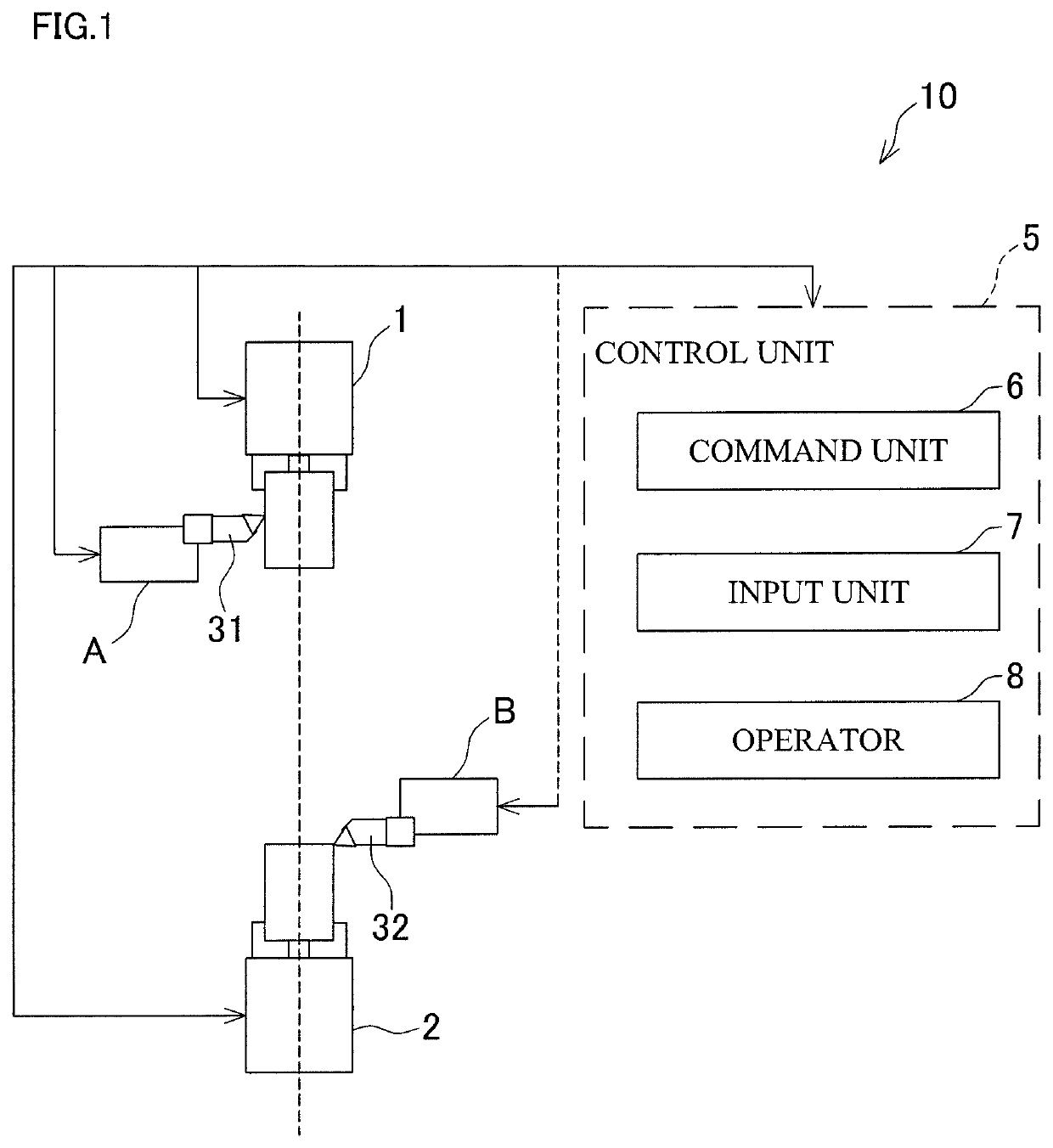
[0021]FIG. 1 is an explanatory view illustrating the NC lathe 10.

[0022]First, a mechanical structure of the NC lathe 10 will be described. The NC lathe 10 includes a main spindle 1 and a sub spindle 2, a tool post A and a tool post B, and a control unit 5. The main spindle 1 and the sub spindle 2 are configured to rotate a chucked workpiece. The tool post A and the tool post B are loaded with cutting-tools 31 and 32, respectively. The control unit 5 controls operations of the main spindle 1 and the sub spindle 2, and the tool post A and the tool post B. The control unit 5 includes an input unit 7, an operator 8, and a command unit 6. The input unit 7 is for an operator to input, for example, a driving command of a motor. The operator 8 is for, for example, interpreting a configured processing program. The command unit 6 is for, for exampl...


PUM

PropertyMeasurementUnit
outer diameteraaaaaaaaaa

Abstract

An operational control method is provided for a machine tool that includes a plurality of tool holders with a cutting-tool. The machine tool relatively moves the tool holders with respect to a workpiece to process the workpiece. The operational control method includes determining whether an abnormality has occurred in the cutting-tool during a processing or not, determining whether a simultaneous processing in which at least two or more of the tool holders perform the processings to an identical workpiece is being performed or not and whether the cutting-tool having the detected abnormality is the cutting-tool that is performing the simultaneous processing or not when the abnormality is detected, and causing the tool holder with the cutting-tool having the detected abnormality to take an abnormality avoidance operation and another of the tool holders to take a response operation based on a determination result at the determining of the simultaneous processing.

Description

BACKGROUND[0001]This application claims the benefit of Japanese Patent Application Number 2017-033858 filed on Feb. 24, 2017, the entirety of which is incorporated by reference.Technical Field[0002]The disclosure relates to an operational control method for, for example, when an abnormality occurs in a cutting-tool during a simultaneous processing where a plurality of tool holders are operated in a machine tool, such as an NC lathe.Related Art[0003]Conventionally, there has been, what is called, a simultaneous processing, a machining method that performs the processing on one workpiece by operating a plurality of tool holders. The simultaneous processing includes, for example, a method that uses an NC lathe that includes a plurality of tool posts holding cutting tools, simultaneously applies the plurality of cutting tools to one workpiece, and simultaneously performs different processings using the respective cutting tools (illustrated in FIG. 3). With such a simultaneous processing...

Claims


Application Information

Patent Timeline
Patent Type & Authority Patents(United States)
IPC IPC(8): B32B7/12B32B1/00B23B7/12B23Q39/02G05B19/4065B23B1/00B23B3/16B23Q39/00
CPCB23B7/12B23B1/00B23Q39/026G05B19/4065B23B3/167B23B2270/36B23B2270/48B23Q2039/008G05B2219/37245G05B2219/37252G05B2219/50203B23Q15/007
Inventor TANAKA, TAKAAKISASAKI, RYOSUKE
Owner OKUMA CORP
Why Eureka
Try Eureka