
Body motion detection device, pitch meter, wristwatch-type information processing device, method for controlling thereof, control program, and storage medium

a technology of body motion and information processing, which is applied in the direction of distance measurement, gymnastic exercise, instruments, etc., can solve the problems of inability to accurately count the number of steps, easy to distinguish between walking and running, and easy to make determinations susceptible to errors, so as to reduce labor for users and accurately measure the pitch

Inactive Publication Date: 2007-05-01
SEIKO EPSON CORP
View PDF11 Cites 101 Cited by
  • Summary
  • Abstract
  • Description
  • Claims
  • Application Information

AI Technical Summary

Benefits of technology

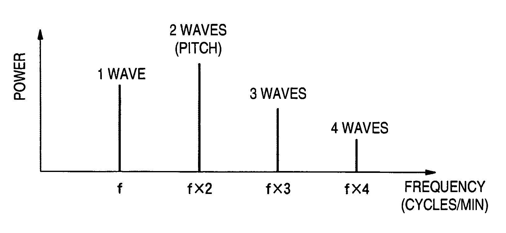
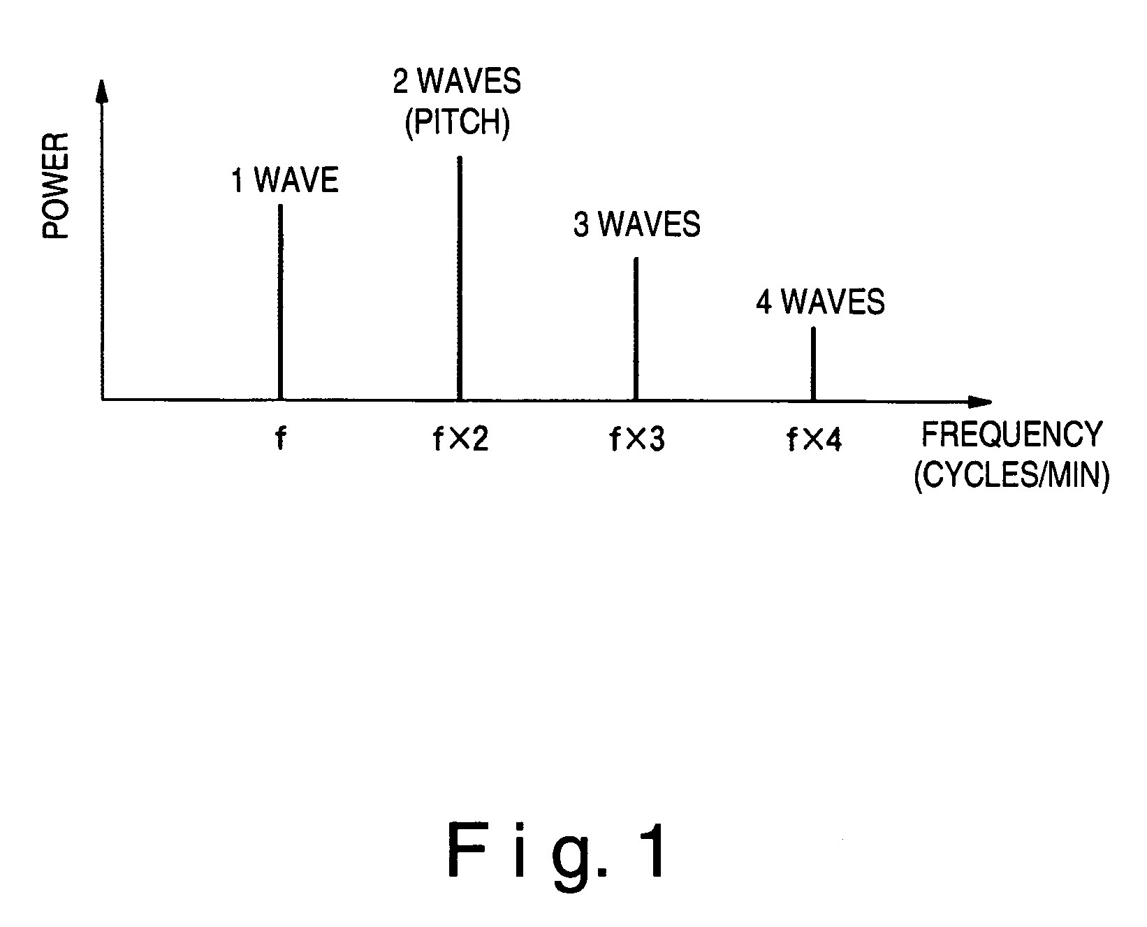
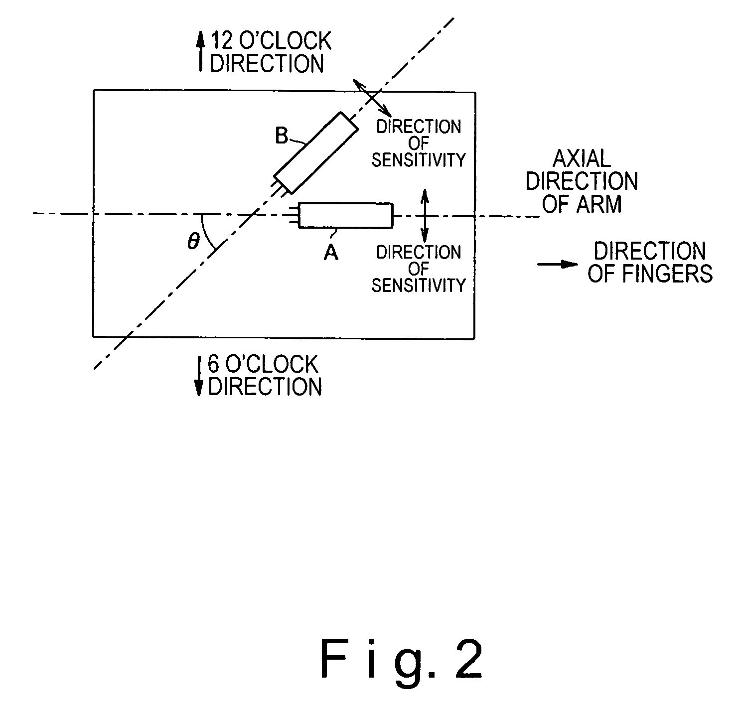
The present invention provides a device for detecting body motion, specifically on the forearm, to measure pitch without distinguishing between running and walking. The device includes a sensor and a component extracting section to extract the body motion component from the sensor's signals. This invention aims to reduce labor for the user and accurately measure pitch.

Problems solved by technology

However, since the characteristics of the waveform of the outputted signal are different between when the user walks with arms extended and when the user runs with arms bent, there are problems in that the number of steps cannot be accurately counted merely by converting the body motion signal to a rectangular waveform.
However, in the above-mentioned conventional pedometer, the counted number cannot be doubled to determine the number of steps and improve the precision of detection if the mask time is not set such that the pulses are counted in a manner in which a single pulse is always counted in the mask time.
However, when the pitch is 80 cycles / min or less, or 160 cycles / min or more, either no pulses are included at all in the mask time or a plurality of pulses are included, which has been the cause of errors.
However, it is difficult to distinguish between a state of walking and a state of running by the pitch waveform alone, and the determinations are susceptible to error.
Also, although the erroneous results can be prevented if the user chooses the operations of the pedometer between a state of walking and a state of running by manual operations every time the user uses the pedometer, problems occur in that ease of use is compromised.
Moreover, as in the above-mentioned conventional method, with a method of calculating the number of steps using rectangular waveform conversion, it has been a problem that when noise gets mixed in or when the operating direction and the direction of sensitivity of the sensor do not coincide, the body motion signal is not clearly outputted in accordance with the leg motion as shown, for example, in FIG. 43.
In such cases, calculation results of the pitch contain large errors.

Method used


Image

  • Body motion detection device, pitch meter, wristwatch-type information processing device, method for controlling thereof, control program, and storage medium
  • Body motion detection device, pitch meter, wristwatch-type information processing device, method for controlling thereof, control program, and storage medium
  • Body motion detection device, pitch meter, wristwatch-type information processing device, method for controlling thereof, control program, and storage medium

Examples


second embodiment

[0124]Referring now to FIGS. 24 and 25, the second embodiment of the present invention is described. The second embodiment of the present invention simplifies the sequence of the frequency analysis process (FFT) for each of the first and second body motion sensors in the above-mentioned first embodiment by performing frequency analysis after combining the output signals from the first and second body motion sensors. Therefore, the second embodiment has basically an identical configuration as the first embodiment, except that a pitch detection device 500 is used instead of the pitch detection device 400 of the first embodiment. In view of the similarity between the first and second embodiments, the parts of the second embodiment that are identical to the parts of the first embodiment will be given the same reference numerals as the parts of the first embodiment. Moreover, the descriptions of the parts of the second embodiment that are identical to the parts of the first embodiment ma...

third embodiment

[0134]Referring now to FIGS. 26–29, the third embodiment of the present invention is explained. The third embodiment of the present invention is configured to combine the output signals of the first and second body motion sensors in the same manner as in the second embodiment. In addition, the third embodiment involves varying the amplification factor in the process of amplifying the two output signals to prevent one output signal from being obscured by the other output signal prior to combining the outputs of the first and second body motion sensors. Furthermore, this embodiment involves using the same amplitude range for the output signals of the first and second body motion sensors. Thus, the third embodiment has basically an identical configuration with the second embodiment, except that the body motion signal converter 502 of the second embodiment is replaced with the body motion signal converter 550 of the third embodiment. In view of the similarity between the first, second a...

fourth embodiment

[0145]Referring now to FIG. 30, the fourth embodiment of the present invention is explained. The fourth embodiment is configured to combine the output signals of the first and second body motion sensors in the same manner as in the second embodiment. Additionally, the fourth embodiment involves changing the amplification factor in the process of amplifying the two output signals to prevent an output signal from being obscured by the other output signal prior to combining the output signals from the first and second body motion sensors. Thus, the fourth embodiment has basically an identical configuration with the second embodiment, except that the body motion signal converter 502 of the second embodiment is replaced with the body motion signal converter 600 of the third embodiment. In view of the similarity between the first, second and fourth embodiments, the parts of the fourth embodiment that are identical to the parts of the first and second embodiments will be given the same ref...


PUM


Abstract

A body motion detection device is provided that is configured to be attached to a forearm of a user to detect a body motion of the human body to detect body motions of the user. The body motion detection device basically comprises a body motion sensor unit and a body motion component extracting section. The body motion sensor unit is configured and arranged to detect an acceleration caused substantially by a movement of the forearm during walking and an acceleration caused substantially by a movement of the forearm during running to output at least one body motion signal. The body motion component extracting section is configured and arranged to extract a body motion component from said at least one body motion signal. Thus, pitch of the user can be measured based on the body motion component both when the user is running and walking.

Description

BACKGROUND OF THE INVENTION[0001]1. Field of the Invention[0002]The present invention relates to a body motion detection device, a pitch meter, a wristwatch-type information processing device, a method for controlling thereof, a control program, and a storage medium. The present invention particularly relates to technology for reliably determining pitch of a user from a detected body motion signal regardless of whether the user is walking or running.[0003]2. Background Information[0004]In a conventional pedometer for measuring the number of steps when a user is running or walking, a body motion signal is detected by an installed acceleration sensor (body motion sensor). As seen in FIG. 42, the obtained body motion signal is converted to a rectangular waveform, and the number of steps is determined from the body motion signal converted to the rectangular waveform. Specifically, when the body motion signal (analog signal) shown in the upper part of FIG. 42 is amplified and then conver...

Claims


Application Information

Patent Timeline
Patent Type & Authority Patents(United States)
IPC IPC(8): G06F15/00A61B5/00A61B5/11A61B5/22G01C21/10G01C22/00G01P15/00G04G99/00G06M1/27G06M3/00G06M7/00
CPCG01C22/006
Inventor AOSHIMA, ICHIROKAWAFUNE, YUTAKA
Owner SEIKO EPSON CORP
Learn More