A
disadvantage of state-of-the-art PDC drag bits is that they may prematurely wear due to
impact failure of the PDC cutters, as such cutters may be damaged very quickly if used in highly stressed or tougher formations composed of limestones, dolomites, anhydrites, cemented sandstones, interbedded formations, also known as transition zones, such as shale with sequences of sandstone, limestone and dolomites, or formations containing hard “stringers.” As noted above, there are additional categories of tools employed in boreholes, which tools employ superabrasive cutting elements for cutting, and which suffer the same deficiencies in the drilling the enumerated formations.
However, such drag bits provide a much-inferior ROP to PDC cutter-equipped bits and so incur substantial additional drilling cost in terms of rig and drilling
crew time on site.
Conventional PDC cutters experience durability problems in
high load applications.
They have an undesirable tendency to crack (including microcracking),
chip,
spall, and break when exposed to hard, tough or highly stressed geologic structures so that the cutters consequently sustain high loads and
impact forces.
They are similarly weak when placed under high loads from a variety of angles.
The durability problems of conventional PDCs are worsened by the dynamic nature of both normal and torsional loading during the drilling process, wherein the bit face moves into and out of contact with the uncut formation material forming the bottom of the
wellbore, the loading being further aggravated in some bit designs and in some formations by so-called bit “whirl.”
The
diamond table / substrate interface of conventional PDCs is subject to high residual stresses arising from formation of the cutting element, as during cooling, the differing coefficients of
thermal expansion of the
diamond and substrate material result in thermally induced stresses.
Both of these phenomena are deleterious to the life of the cutting element during drilling operations as the stresses, when augmented by stresses attributable to the loading of the cutting element by the formation, may cause spalling, fracture or even
delamination of the
diamond table from the substrate.
Further, high tangential loading of the cutting edge of the cutting element results in bending stresses on the diamond table, which is relatively weak in tension and will thus fracture easily if not adequately supported against bending.
The
metal carbide substrate on which the diamond table is formed may be of inadequate stiffness to provide a desirable degree of such support.
The relatively rapid wear of diamond tables of conventional PDC cutters also results in rapid formation of a wear flat in the
metal carbide substrate backing the cutting edge, the wear flat reducing the per-unit area loading in the vicinity of the cutting edge and requiring greater
weight on bit (WOB) to maintain a given
rate of penetration (ROP).
The wear flat, due to the introduction of the substrate material as a contact surface with the formation, also increases drag or frictional contact between the cutter and the formation due to modification of the
coefficient of friction.
As one result, frictional
heat generation is increased, elevating temperatures in the cutter and initiating damage to the PDC table in the form of heat checking while, at the same time, the presence of the wear flat reduces the opportunity for access by
drilling fluid to the immediate rear of the cutting edge of the diamond table.
The cutter loading may otherwise cause chipping or spalling of the diamond layer at an unchamfered cutting edge shortly after a cutter is put into service and before the cutter naturally abrades to a flat surface, or “wear flat,” at the cutting edge.
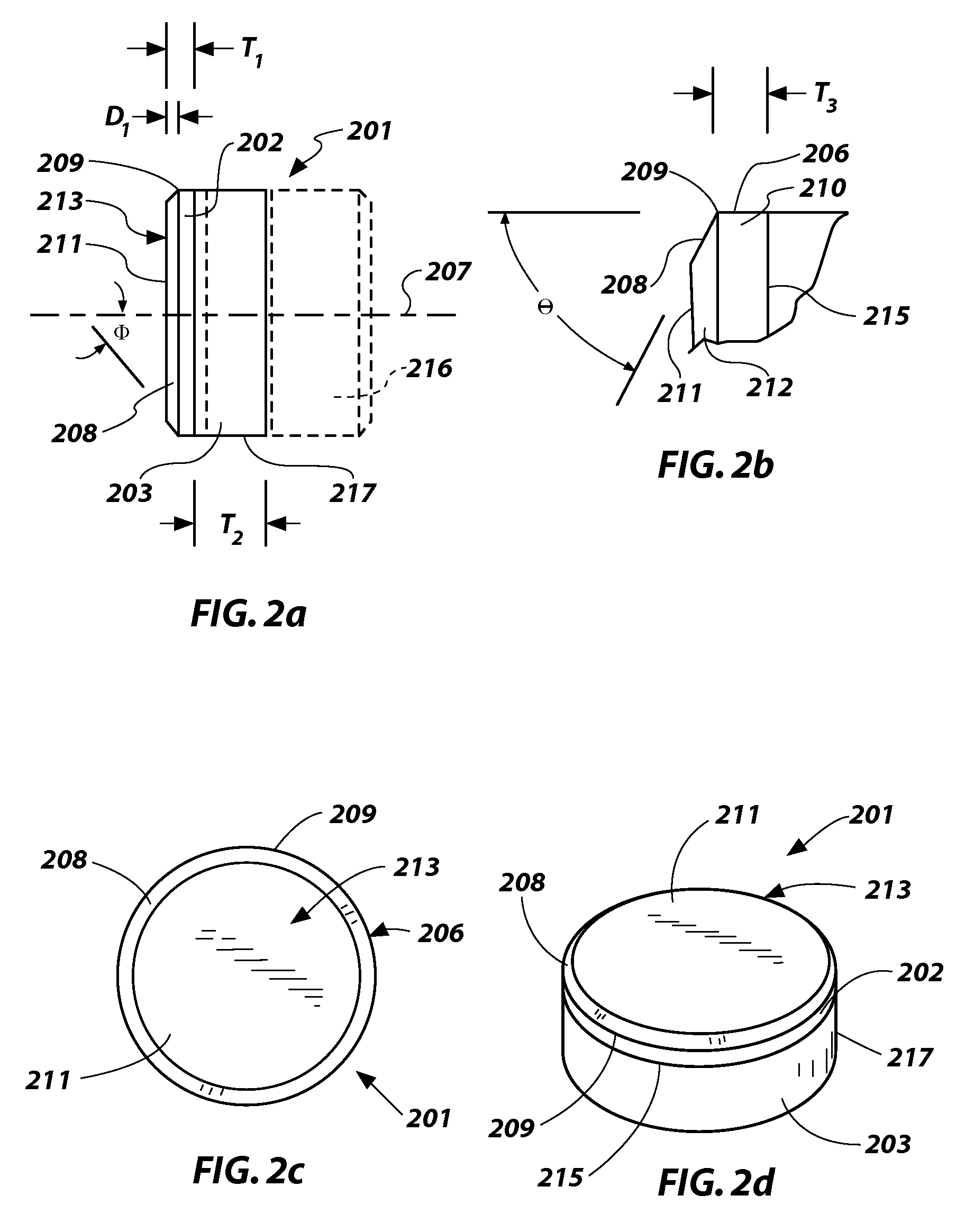
It is known that conventionally providing larger chamfers on cutters enhances durability, but at the same time reduces ROP and undesirably increases required WOB for a given ROP.
It has been found that the cutter in PDC form may tend to show some cracks after use, but the small cracks do not develop into a
catastrophic failure of the diamond table as typically occurs in PDC cutters.
While such PDC cutters, with their large rake lands, have shown some promise in initial field testing, conclusively proving the durability of the design when compared to other cutters of similar diamond table thickness but without the large rake land, these PDC cutters also demonstrated some disadvantageous characteristics which impaired their usefulness in real-world drilling situations.
Specifically,
drill bits equipped with these PDC cutters demonstrated a disconcerting tendency, apparently due to the extraordinarily great cutting forces generated by contact of these cutters with a formation being drilled, to overload drilling motors, other bottomhole
assembly (BHA) components such as subs and housings, as well as tubular components of the
drill string above the BHA.
Further, bits equipped with these PDC cutters often drilled significantly slower, that is to say, their
rate of penetration (ROP) of the formation was far less than, the ROP of bits equipped with conventional PDC cutters, and also exhibited difficulty in drilling through hard formations for which they would be otherwise ideally suited.
It appears that the exterior configuration of these thick diamond table cutters, although contributing to the robust nature of the cutters, may be less than ideal for many drilling situations due to the
variable geometry of the arcuate rake land as it contacts the formation and attendant lack of “aggressiveness” in contacting and cutting the formation.
Therefore, despite the favorable characteristics exhibited by these PDC cutters, their utility in efficiently cutting the difficult formations for which its demonstrated durability is ideally suited remains, as a practical matter, unrealized over a broad range of formations and drilling conditions.
These PDC cutters are described as durable, fairly aggressive and providing a more consistent performance over the life of the cutter than the PDC cutters described in the '906 patent, but their large chamfers result in an unacceptable reduction in aggressivity in cutting, leading to a reduced ROP.
Such a geometry has been demonstrated to inhibit initial chipping of a PDC cutter along the cutting edge, prolonging the life thereof.
During
laboratory testing, it has been observed that conventional, 45° chamfer angle cutters with conventional chamfer depths on the order of, for example, 0.016 inch, commonly experience premature cutter damage and failure when the wear flat extends inwardly of the inner boundary of the chamfer.
Specifically, an increased incidence of spalling and chipping of the PDC table has been observed.
This is a particular problem in the aforementioned highly stressed or tougher formations, interbedded formations and formations containing hard stringers.
However, when the inner edge or boundary of the chamfer is worn away, the chamfer component of the compressive forces is diminished, with a consequent potential for high
tensile shear forces to be present at the cutting face, resulting in the aforementioned spalling and chipping.
In addition, heat checking in the PDC table, due to the
initiation of a large, relatively wide wear flat is particularly significant toward the rear of the wear flat and may result in significant breakage of the PDC table at the back and sides thereof.


