Methods and apparatus for performing flue gas pollution control and/or energy recovery
a technology of flue gas pollution control and energy recovery, applied in heat recovery, emissions prevention, separation processes, etc., can solve the problems of high capital and operating costs, high cost of wesp pollution control devices, and generally very expensive alloys, so as to avoid, eliminate or reduce any need, improve system efficiency, avoid clogging and clumping problems
- Summary
- Abstract
- Description
- Claims
- Application Information
AI Technical Summary
Benefits of technology
Problems solved by technology
Method used
Image
Examples
embodiment 500
[0064]FIG. 5 shows an embodiment 500 similar to that of FIG. 4 but with the injection point of the collected fly ash being upstream of the AH 309 at the location of injection nozzle 504 which is inside the duct 508 connecting the SCR 306 to the AH 309. Ash is supplied to nozzle 504 via pipe 502 which in the FIG. 5 embodiment is connected to the ash hoppers on the particulate collection device 424.
embodiment 600
[0065]FIG. 6 illustrates an embodiment 600 which is similar to that of FIG. 3 but with ash being collected in a hopper, represented as a triangle at the bottom of the AH 602, located at the AH 602. Control module 626 controls' a blower 618 and value 614 which is used to control the flow of ash from the hopper at the AH 602 to an injection nozzle 608 via pipe 610. The injection nozzle 608 is located in a duct 606 positioned between the AH 602 and gas cooler 408. Excess ash is discharged from the AH hopper for disposal via pipe 612.
embodiment 700
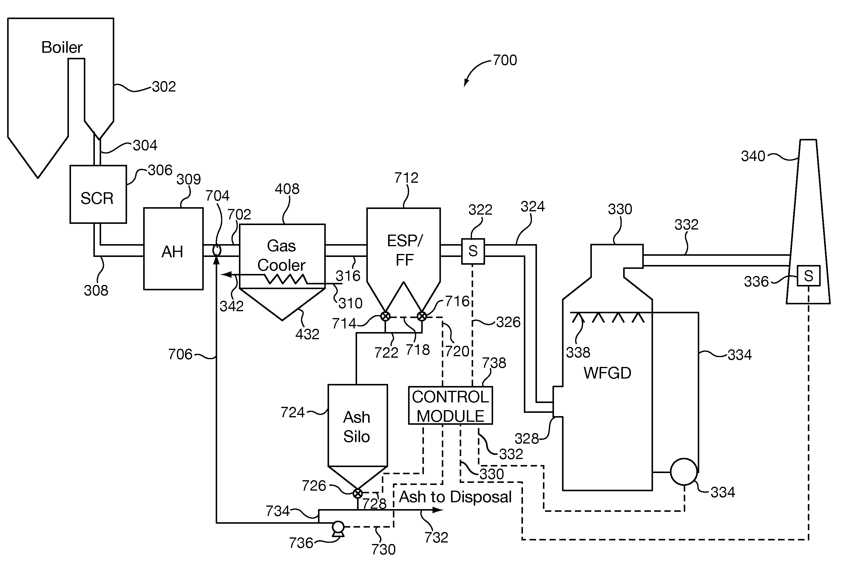
[0066]FIG. 7 illustrates an embodiment 700 in which ash is collected from hoppers located on the particulate removal device 712 and / or other collection points in the system. The collected ash from device 712 is supplied to an ash silo 724 via control valves 714, 716. The output of an ash hopper 432 on the gas cooler 408 and / or an ash hopper on the AH 309 may, and in some embodiments are, also coupled to an ash input of the ash silo 724 where ash is collected and stored prior to reuse and / or disposal. Control module 738 controls operation of the various valves 714, 716, 726 and blowers 736 via control lines 718, 720, 728, and 730. The output of ash silo 724 is supplied via valve 726 and pipe 706 to an ash injection nozzle 704 and / or to an ash disposal outlet via pipe 732. In the FIG. 7 embodiment, the ash injection nozzle 704 is positioned between the AH 309 and gas cooler 408 in duct 702.
[0067]As discussed above, to facilitate mercury capture, in some embodiment activated carbon is ...
PUM
| Property | Measurement | Unit |
|---|---|---|
| temperatures | aaaaa | aaaaa |
| corrosion-resistant | aaaaa | aaaaa |
| power consumption | aaaaa | aaaaa |
Abstract
Description
Claims
Application Information
 - R&D
- Intellectual Property
- Life Sciences
- Materials
- Tech Scout
- Unparalleled Data Quality
- Higher Quality Content
- 60% Fewer Hallucinations
Browse by: Latest US Patents, China's latest patents, Technical Efficacy Thesaurus, Application Domain, Technology Topic, Popular Technical Reports.
© 2025 PatSnap. All rights reserved.Legal|Privacy policy|Modern Slavery Act Transparency Statement|Sitemap|About US| Contact US: help@patsnap.com


