
Organic/inorganic composite porous layer-coated electrode and electrochemical device comprising the same

a composite porous, electrode technology, applied in the field of electrochemical devices, can solve the problems of complex manufacturing process, limited safety of batteries in terms of ignition and combustion, and explosion of batteries, and achieve the effect of improving the performance and safety of an electrochemical devi

Active Publication Date: 2010-03-23
LG ENERGY SOLUTION LTD
View PDF34 Cites 88 Cited by
  • Summary
  • Abstract
  • Description
  • Claims
  • Application Information

AI Technical Summary

Benefits of technology

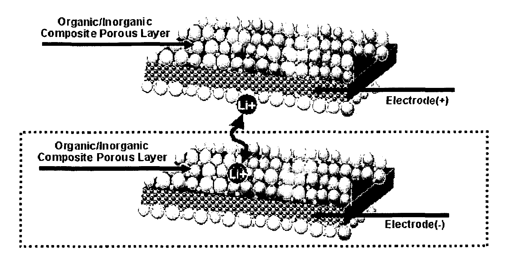
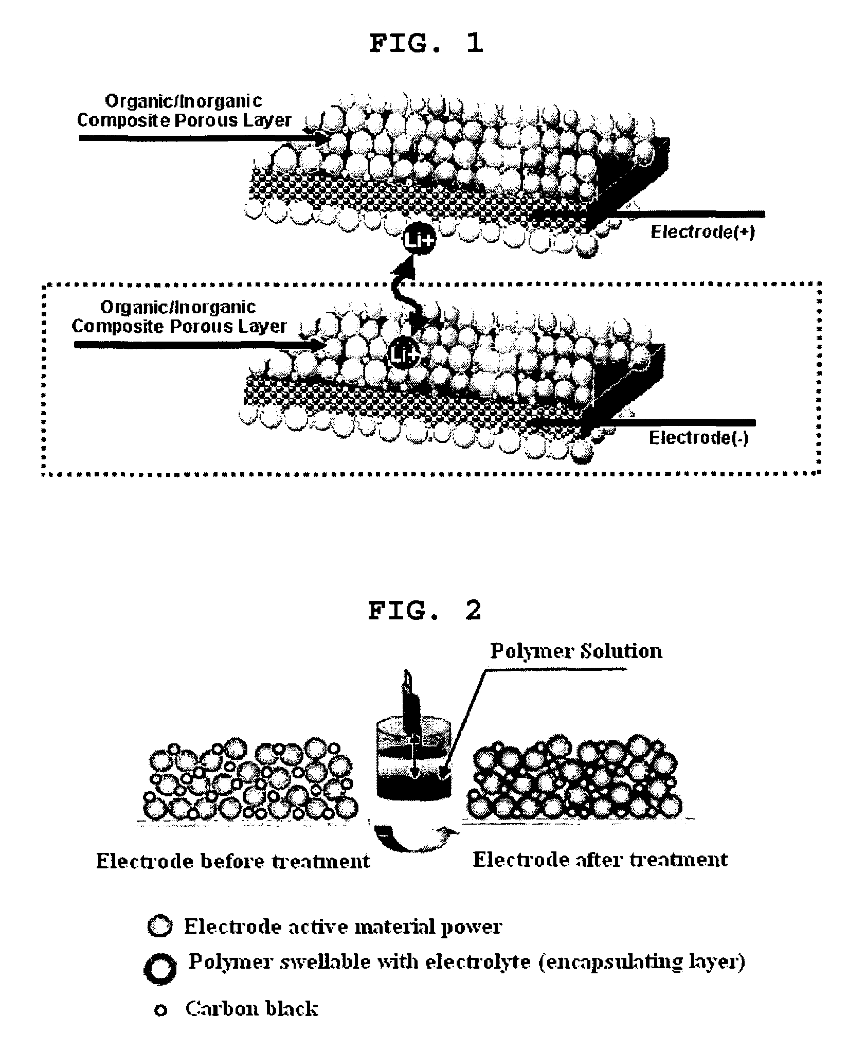
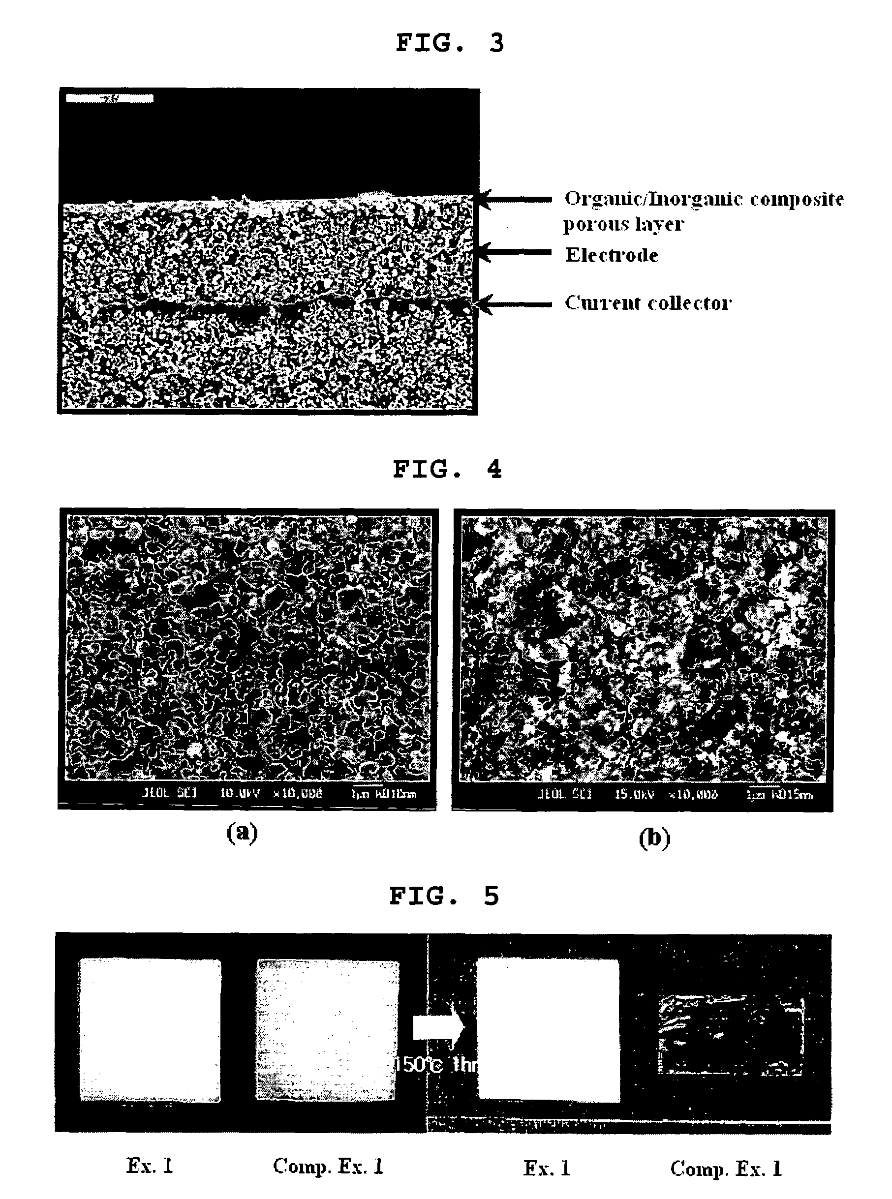
The present invention provides an electrode with an organic / inorganic composite porous coating layer that can function as a separator and improve the performance and safety of an electrochemical device. The coating layer is formed by coating a mixture of inorganic particles with a binder polymer on the surface of an electrode, which prevents short circuit between a cathode and an anode and has excellent safety characteristics compared to conventional batteries. The coating layer can also be controlled to have a uniform pore size and porosity, and can improve the performance of an electrochemical device compared to conventional organic / inorganic composite electrolytes. The electrode with the organic / inorganic composite porous coating layer can be easily manufactured by coating a slurry of inorganic particles and a binder polymer on the surface of a preformed electrode.

Problems solved by technology

However, such lithium secondary batteries have disadvantages in that organic electrolytes used therein may cause safety-related problems resulting in ignition and explosion of the batteries and that processes for manufacturing such batteries are complicated.
For this purpose, safety of batteries is strictly restricted in terms of ignition and combustion in batteries by safety standards.
However, use of a protection circuit causes limitation in downsizing and cost reduction of a battery pack.
A mechanism of heat occlusion by a separator often acts inefficiently, when heat emission is generated rapidly.
However, safety mechanisms based on electrolyte additives have disadvantages in that calorific values (J) may be varied depending on charging current or internal resistance of a battery and that timing is not uniform.
Moreover, the above conventional safety means are always followed by degradation of other battery qualities.
However, such methods have a disadvantage in that they cause degradation in battery performance even if the battery safety may be improved, because the inorganic particles as coating agent have no lithium ion conductivity.
Meanwhile, electrochemical devices such as lithium ion batteries have problems related with currently used separator in addition to the above safety problems.
However, such polyolefin-based separators have a disadvantage in that they can be shrunk into their original sizes by heating at high temperature due to the properties of the materials for separators such as melting of polyolefin-based materials at 200° C. or less, and processing characteristics such as stretching of the materials for controlling pore sizes and porosity.
Therefore, when a battery is heated to high temperature by internal / external factors, there is a great possibility of short-circuit between a cathode and an anode caused by shrinking or melting of separators, resulting in accidents such as explosion of a battery caused by emission of electric energy.
However, it is known that such composite electrolytes serving as a substitute for a conventional separator and liquid electrolyte are not advisable, because such composite electrolytes have low ion conductivity compared to liquid electrolytes, the interfacial resistance between the inorganic materials and the polymer is high while they are mixed, such composite electrolytes cannot be easily handled due to the brittleness thereof when an excessive amount of inorganic materials is introduced, and it is difficult to assemble batteries using such composite electrolytes.
However, the polymer used in such electrolytes has poor binding ability so that a great amount of inorganic materials cannot be used.
Further, such gel type polymer electrolytes have low ion conductivity compared to liquid electrolytes, resulting in degradation of battery performance.
However, it is practically difficult to apply such electrolyte in batteries due to poor mechanical properties such as high brittleness of the film.
However, because such films still use a polyolefin-based separator, they have a disadvantage in that it is not possible to obtain a significant improvement in safety including prevention of heat shrinking at high temperature.
However, the Creavis's composite separator cannot provide excellent mechanical properties due to the basic characteristics of non-woven webs.
Moreover, because the chemical structure of polyester is fragile to electrochemical reactions, the Creavis's composite separator is expected to have many difficulties in practical use in batteries [“Desalination”-vol.

Method used


Image

  • Organic/inorganic composite porous layer-coated electrode and electrochemical device comprising the same
  • Organic/inorganic composite porous layer-coated electrode and electrochemical device comprising the same
  • Organic/inorganic composite porous layer-coated electrode and electrochemical device comprising the same

Examples


examples 1-9

Example 1

Organic / Inorganic Composite Porous Coating Layer-Coated Electrode and Manufacture of Lithium Secondary Battery Comprising the Same

[0092]1-1. Electrode Having Organic / Inorganic Composite Porous Coating Layer (PVdF-CTFE / Al2O3)

[0093](Manufacture of Anode)

[0094]To N-methyl-2-pyrrolidone (NMP) as a solvent, 96 wt % of carbon powder as an anode active material, 3 wt % of PVDF (polyvinylidene fluoride) as a binder and 1 wt % of carbon black as a conductive agent were added to form mixed slurry for an anode. The slurry was coated on. Cu foil having a thickness of 10 μm as an anode collector and dried to form an anode. Then, the anode was subjected to roll press.

[0095](Manufacture of Cathode)

[0096]To N-methyl-2-pyrrolidone (NMP) as a solvent, 92 wt % of lithium cobalt composite oxide (LiCoO2) as a cathode active material, 4 wt % of carbon black as a conductive agent and 4 wt % of PVDF (polyvinylidene fluoride) as a binder were added to form slurry for a cathode. The slurry was coate...

example 2

[0101]Example 1 was repeated to provide an electrode having an organic / inorganic composite porous coating layer (PVdF-CTFE / BaTiO3) and a lithium secondary battery, except that BaTiO3 powder was used instead of alumina (Al2O3) powder, as inorganic particles in the coating material on the electrode surface.

example 3

[0102]Example 1 was repeated to provide an electrode having an organic / inorganic composite porous coating layer (PVdF-CTFE / PMN-PT) and a lithium secondary battery, except that PMN-PT(lead magnesium niobate-lead titanate) powder was used instead of alumina (Al2O3) powder, as inorganic particles in the coating material on the electrode surface.


PUM

PropertyMeasurementUnit
particle diameteraaaaaaaaaa
pore sizeaaaaaaaaaa

Abstract

Disclosed is an electrode comprising a first organic / inorganic composite porous coating layer formed on its surface, wherein the first coating layer includes inorganic particles and a binder polymer for interconnecting and fixing the inorganic particles, and has micropores formed by interstitial volumes among the inorganic particles. An electrochemical device including the same electrode is also disclosed. Further, disclosed is a method for manufacturing an electrode having an organic / inorganic composite porous coating layer on the surface thereof, comprising the steps of: (a) coating a current collector with slurry containing an electrode active material and drying it to provide an electrode; and (b) coating the surface of electrode obtained from step (a) with a mixture of inorganic particles with a binder polymer. A lithium secondary battery including the electrode shows improved safety and minimized degradation in battery performance.

Description

[0001]This application claims the benefit of the filing dates of Korean Patent Application Nos. 10-2004-0008136, filed on Feb. 7, 2004 and 10-20040008585, filed on Feb. 10, 2004, in the Korean Intellectual Property Office, the disclosures of which are incorporated herein in its entirety by references.TECHNICAL FIELD[0002]The present invention relates to an electrode that can improve performance and safety of an electrochemical device, more particularly an electrode having a coating layer serving as a substitute for a separator, a method for manufacturing the same, and an electrochemical device comprising the same.BACKGROUND ART[0003]Recently, there is an increasing interest in energy storage technology. Batteries have been widely used as energy sources in portable phones, camcorders, notebook computers, PCs and electric cars, resulting in intensive research and development into them. In this regard, electrochemical devices are subjects of great interest. Particularly, development of...

Claims


Application Information

Patent Timeline
Patent Type & Authority Patents(United States)
IPC IPC(8): H01M4/62H01M2/16H01M4/02H01M4/137H01M10/05
CPCH01M2/166H01M4/04H01M4/0402H01M4/0404H01M4/0416H01M4/0435H01M4/13H01M4/139H01M2/1673Y02E60/122H01M10/052H01M2004/027H01M2004/028H01M2300/0025H01M2300/0065H01M2300/0091H01M2300/0094H01M50/446H01M50/46Y02E60/10E04G21/123
Inventor YONG, HYUN HANGLEEKIM, SEOK KOOAHN, SOON HO
Owner LG ENERGY SOLUTION LTD
Learn More