Transmission component, method of manufacturing the same, and tapered roller bearing

a technology of transmission components and tapered roller bearings, which is applied in the direction of gearing details, solid state diffusion coating, hoisting equipment, etc., can solve the problems of difficult to achieve the number of grain grains exceeding 13 and achieve the effects of enhancing dimensional stability, long fatigue life, and increasing anti-crack strength

Active Publication Date: 2010-03-23
NTN CORP
View PDF156 Cites 7 Cited by
  • Summary
  • Abstract
  • Description
  • Claims
  • Application Information

AI Technical Summary

Benefits of technology

The present invention provides a transmission component that has increased anti-crack strength, dimensional stability, and long fatigue life. The component has a nitriding layer at a surface layer with a small austenite grain size, which allows for improved resistance to cracking and rolling contact fatigue. The component also has a fracture stress value of at least 2650 MPa, making it stronger than conventional components. Additionally, the present invention provides a method of manufacturing the transmission component by carbonitriding and cooling the steel to a specific temperature range. The method results in a fine austenite grain size and improved performance of the component.

Problems solved by technology

Although further finer austenite grains are desirable, the grain size number exceeding 13 is usually difficult to achieve.

Method used


Image

  • Transmission component, method of manufacturing the same, and tapered roller bearing
  • Transmission component, method of manufacturing the same, and tapered roller bearing
  • Transmission component, method of manufacturing the same, and tapered roller bearing

Examples


example 1

[0094]JIS-SUJ2 (1.0 wt % of C-0.25 wt % of Si-0.4 wt % of Mn-1.5 wt % of Cr) was used for Example 1 of the present invention. Samples shown in Table 1 were each produced through the procedure described below.

[0095]

TABLE 1ConventionallyNormallycarbonitridedquenchedSamplesABCDEFproductproductSecondary7801)800815830850870——quenchingtemp.(° C.)Hydrogen—0.370.400.380.420.400.720.38content(ppm)Grain size No.—1211.51110101010(JIS)Charpy impact—6.656.406.306.206.305.336.70value (J / cm2)Fracture stress—2840278026502650270023302770value(MPa)Rolling contact—5.44.23.52.92.83.11fatigue liferatio (L10)1)Not evaluated this time due to insufficient quenching.

[0096]Samples A-D: Examples of the Present Invention

[0097]Carbonitriding was performed at 850° C. held for 150 minutes in an atmosphere of a mixture of RX gas and ammonia gas. Following the heat treatment pattern shown in FIG. 3, primary quenching was done from a carbonitriding temperature of 850° C., and secondary quenching was subsequently don...

example 2

[0146]Example 2 of the present invention is now described.

[0147]On the following samples A, B and C, a series of tests was conducted. A material to be heat-treated that was employed commonly to samples A-C was JIS-SUJ2 (1.0 wt % of C-0.25 wt % of Si-0.4 wt % of Mn-1.5 wt % of Cr). Samples A-C were each processed through the following procedure.

[0148]Sample A—comparative example: normal quenching only (without carbonitriding)

[0149]Sample B—comparative example: quenching directly after carbonitriding (conventional carbonitriding and quenching)

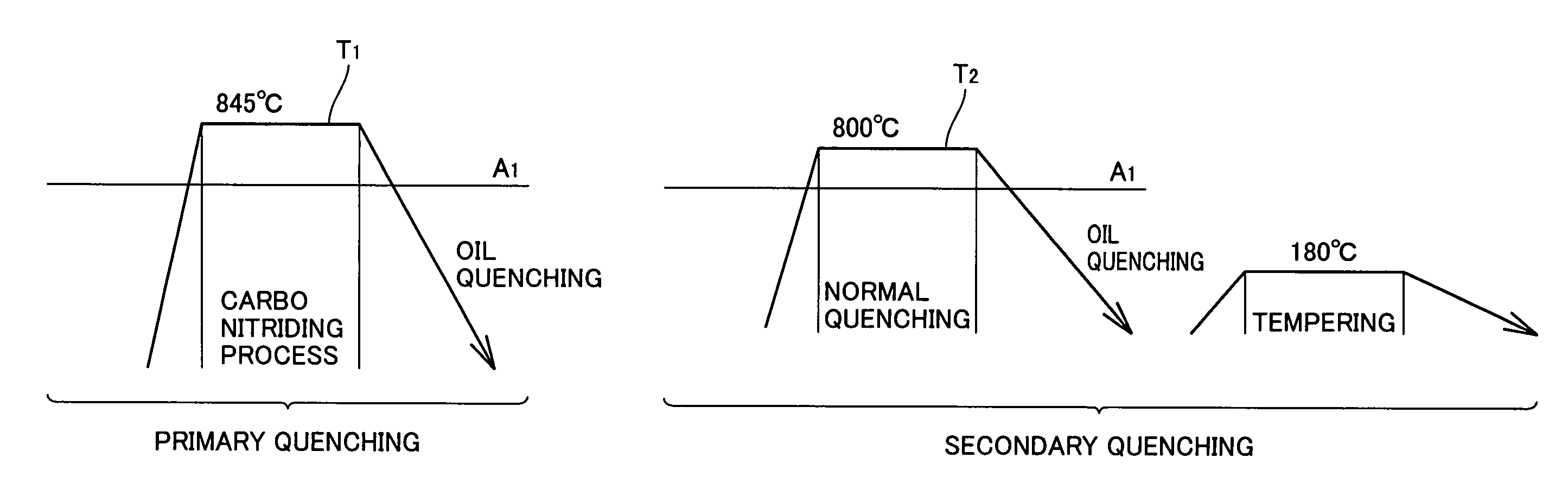
Carbonitriding was conducted at 845° C. held for 150 minutes. The atmosphere in the carbonitriding process was a mixture of RX gas and ammonia gas.

[0150]Sample C—example of the present invention: A bearing material was processed following the heat treatment pattern shown in FIG. 2. carbonitriding was conducted at 845° C. held for 150 minutes. The atmosphere in the carbonitriding process was a mixture of RX gas and ammonia gas. Final quenching tem...


PUM

PropertyMeasurementUnit
temperatureaaaaaaaaaa
grain sizeaaaaaaaaaa
grain diameteraaaaaaaaaa

Abstract

A transmission component is incorporated into a transmission in which an input shaft, an output shaft, or a gear is rotatably supported by a rolling bearing. The component has a nitriding layer at a surface layer and an austenite grain with a grain size number falling within a range exceeding 10. This provides a transmission component having an increased anti-crack strength, enhanced dimensional stability, and a long fatigue life. A method of manufacturing such a transmission component and a tapered roller bearing are also provided.

Description

BACKGROUND OF THE INVENTION[0001]1. Field of the Invention[0002]The present invention relates to a transmission component having a long rolling contact fatigue life, an increased anti-crack strength, or a reduced secular variation in dimension, and to a method of manufacturing the same and a tapered roller bearing.[0003]2. Description of the Background Art[0004]To increase a bearing's components in life, a thermal treatment is performed. Specifically, for example, in quenching the components they are heated in an ambient RX gas with ammonium gas further introduced therein to carbo-nitride their surface layer portion, for example as disclosed in Japanese Patent Laying-Open Nos. 8-4774 and 11-101247. This carbonitriding process can harden the surface layer portion and generate retained austenite in a microstructure to provide increased rolling contact fatigue life.[0005]The above-mentioned carbonitriding process is a process to diffuse carbon and nitrogen. This requires a high tempera...

Claims


Application Information

Patent Timeline
Patent Type & Authority Patents(United States)
IPC IPC(8): F16C33/58F16C33/00C23C8/26C23C8/30C23C8/32F16C33/30F16C33/32F16C33/34F16C33/36F16C33/62F16C33/64F16H55/06F16H57/02
CPCC23C8/32F16C33/64F16C33/30F16H57/021F16C33/32F16C33/34
Inventor OKUGAMI, KOUICHIMURAMATSU, YOSHINORIOHKI, CHIKARAHORI, MICHIO
Owner NTN CORP
Why Eureka
Try Eureka