Development roller

a technology of development rollers and rollers, which is applied in the direction of shafts and bearings, coatings, instruments, etc., can solve the problems of disadvantageous peeling of coating films, insufficient adhesion between elastic layers and coating films of water-based paints, and inability to achieve desired surface roughness of rollers to be finally obtained, etc., to achieve the effect of ensuring the hardness of the roller

Inactive Publication Date: 2009-04-28
BRIDGESTONE CORP
View PDF7 Cites 9 Cited by
  • Summary
  • Abstract
  • Description
  • Claims
  • Application Information

AI Technical Summary

Benefits of technology

[0009]Accordingly, an object of the present invention is to provide a development roller which can ensure desired roughness and roller hardness even when an elastic layer has not sufficient solvent resistance, and which can be preferably used for a long period of time without generating peeling of a coating film during a continuous long operation.
[0010]Through intensive research carried out by the inventor of the present invention, it was discovered that when a coating film formed from a chloroprene-methacrylic acid copolymer used as a water-based resin is provided on an elastic layer, peeling of the coating film at the surface of the elastic layer can be prevented and that the above-described problems can be solved, and as a result, the present invention was made.
[0013]According to the present invention, by forming the underlying conductive layer primarily composed of a chloroprene-methacrylic acid copolymer, that is a water-based resin, on the elastic layer, although having not sufficient solvent resistance, the elastic layer can be prevented from being roughened which is caused by a solvent, and a desired surface roughness and roller hardness can be ensured. In addition, the coating film is not peeled away even during a continuous long operation, and as a result, a development roller which can be preferably used for a long period of time can be realized.

Problems solved by technology

However, when the coating film is formed on the elastic layer, depending on the solvent resistance thereof, the surface of the elastic layer may be dissolved with a solvent contained in the paint, and as a result, the desired surface roughness of the roller to be finally obtained may not be ensured in some cases.
However, according to the water-based resins which have been investigated, adhesion between the elastic layer and the coating film of the water-based paint is not sufficient in particular in the case of a roller such as a development roller which is driven by itself, and as a result, the coating film is disadvantageously peeled away during a continuous long operation.

Method used


Image

  • Development roller
  • Development roller
  • Development roller

Examples


example 1

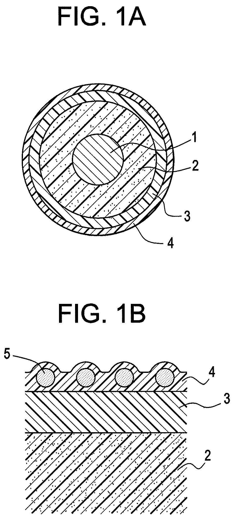
[0037]First of all, to the periphery of a core bar 1 (8 mm in diameter, 260 mm in length, material: sulfur free-cutting steel), a polyurethane foam was fixed by a mechanical froth method.

[0038]In particular, a polyurethane raw material containing 100 parts by weight of an isocyanate component (prepolymerized isocyanate TDI+polyol), 20 parts by weight of a polyol component (polyether polyol), 2 parts by weight of carbon black (acetylene black), and 0.2 parts by weight of an ion conductive agent (sodium perchlorate) was prepared and was then mechanically stirred while dry air was mixed with the polyurethane raw material, so that foaming was performed. This foamed polyurethane raw material was charged in a split metal mold having a cylindrical shape, the mold having holes at end portions thereof through which a shaft was held and having metal caps supporting the shaft. Inside the mold, the core bar 1 provided with an adhesive around the periphery thereof was placed. Subsequently, the m...

examples 2 to 5

[0040]Development rollers were formed in a manner similar to that in Example 1 except that the thickness of the underlying conductive layer 3 was set to 8, 10, 100, and 105 μm. The surface roughness of the rollers thus formed was in the range of 0.6 to 1.5 μm in terms of the arithmetic average roughness Ra in accordance with JIS.

example 6

[0041]A development roller was formed in a manner similar to that in Example 1 except that a water-based paint composed of 100 parts by weight of a chloroprene-methacrylic acid copolymer (trade name: Shoprene SRX-1412, manufactured by Showa Denko K. K.) and 3.5 parts by weight of carbon black (Ketjen black) blended therewith was applied as a first sublayer by dip coating onto the cured polyurethane foam removed from the mold to form a coating film having a thickness of 10 μm, and that as a second sublayer, dip coating of an acrylic emulsion containing carbon black (Ketjen black) was performed to form a coating film having a thickness of 50 μm so that the underlying conductive layer 3 was formed to have a total thickness of 60 μm. The surface roughness of the roller thus formed was 0.6 to 1.5 μm in terms of the arithmetic average roughness Ra in accordance with JIS.


PUM


Abstract

A development roller is provided which can ensure a desired surface roughness and roller hardness even when an elastic layer has not sufficient solvent resistance and which can be preferably used for a long period of time without generating any peeling of a coating film during a continuous long operation. In the development roller, an underlying conductive layer having at least one sublayer and a surface resin layer are provided on the elastic layer in that order. The elastic layer is formed of a foam material having a closed cell structure, the underlying conductive layer is formed from a water-based paint containing a conductive agent, and one of the sublayers of the underlying conductive layer that is in contact with the elastic layer is at least primarily composed of a chloroprene-methacrylic acid copolymer.

Description

BACKGROUND OF THE INVENTION[0001]1. Field of the Invention[0002]The present invention relates to a development roller (hereinafter simply referred to as a “roller” in some cases), and more particularly relates to a development roller used in a development process performed by an image forming device using an electrophotographic system.[0003]2. Description of the Related Art[0004]In an image forming device, such as a copying machine or a printer, using an electrophotographic system, roller members having conductivity are used in individual electrophotographic processes, such as development, electrification, and transfer (toner supply and cleaning).[0005]Heretofore, as conductive rollers used as a development roller, an electrification roller, a transfer roller (toner supply and cleaning) and the like, a basic structure has been used in which a conductive elastic layer composed of a conductive rubber, high molecular weight elastomer, high molecular weight foam, or the like, which has ...

Claims


Application Information

Patent Timeline
Patent Type & Authority Patents(United States)
IPC IPC(8): G03G15/08
CPCG03G15/0818G03G2215/0861
Inventor KAWANO, KOTASUGIMURA, TAKAYUKIMIYAZAKI, KENICHI
Owner BRIDGESTONE CORP
Why Eureka
Try Eureka