Electrolyte membrane for fuel cell operable in medium temperature range, fuel cell using the same, and manufacturing methods therefor

a technology of electrolyte membrane and fuel cell, which is applied in the direction of sustainable manufacturing/processing, non-metal conductor manufacturing, and final product manufacturing, etc., can solve the problems of reducing the resistance of the membrane, difficult to form a dense thin membrane on an electrode formed from a porous material, and increasing the resistance of the electrolyte membrane. , to achieve the effect of reducing the operating temperature range of the low temperature fuel cell and suppressing the resistance of the electrolyte membran

Active Publication Date: 2009-02-17
TOYOTA JIDOSHA KK
View PDF29 Cites 2 Cited by
  • Summary
  • Abstract
  • Description
  • Claims
  • Application Information

AI Technical Summary

Benefits of technology

[0010]According to a first aspect of the invention, an electrolyte membrane is provided for a fuel cell that is operable in a medium temperature range. This electrolyte membrane has a three-layer structure including a hydrated electrolyte layer containing moisture and dense layers which are made of a hydrogen permeable material and which are formed on both sides of the electrolyte layer. Both sides of the hydrated electrolyte layer are covered by the dense layers. Thus, even when the fuel cell is operated at high temperature, evaporation of moisture contained in the hydrated electrolyte layer can be inhibited. Moreover, increase in the resistance of the electrolyte membrane can be suppressed. Consequently, the range of the operating temperature of the low temperature fuel cell can be enlarged by using such an electrolyte membrane.
[0012]According to a third aspect of the invention, an electrolyte membrane is provided that includes a substrate formed from a dense hydrogen permeable material and an inorganic electrolyte layer formed on at least one side of the substrate. By forming the electrolyte membrane on the dense substrate, the electrolyte layer can be formed so as to be sufficiently thin. For example, although the thickness of a conventional electrolyte layer is larger than or equal to 10 μm, the thickness of the electrolyte layer according to the invention can be reduced to around 0.1 μm to 1 μm. Consequently, the operating temperature of the high temperature fuel cell can be reduced to a low temperature by using the electrolyte membrane according to the invention.

Problems solved by technology

However, there is a tendency for the resistance of such an electrolyte membrane to increase, as the temperature lowers.
Although the resistance of the membrane can be reduced by decreasing the thickness of the electrolyte membrane, it is very difficult to form a dense thin membrane on an electrode formed from a porous material.
Therefore, it has not been possible to provide a sufficiently thin electrolyte membrane.
In turn, this leads to constraints on design.

Method used


Image

  • Electrolyte membrane for fuel cell operable in medium temperature range, fuel cell using the same, and manufacturing methods therefor
  • Electrolyte membrane for fuel cell operable in medium temperature range, fuel cell using the same, and manufacturing methods therefor
  • Electrolyte membrane for fuel cell operable in medium temperature range, fuel cell using the same, and manufacturing methods therefor

Examples


first embodiment

[0031]the invention is described herein below.

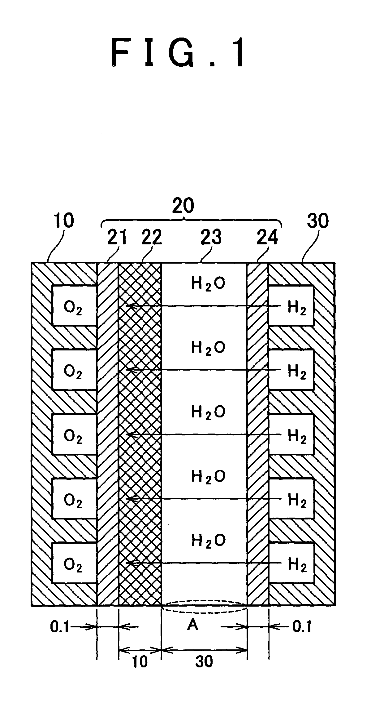
[0032]FIG. 1 is an explanatory view schematically illustrating the configuration of a solid polymer membrane fuel cell according to the first embodiment of the invention. The figure shows a cross-section of a constituent cell of the fuel cell. This constitute cell has a structure in which an electrolyte membrane 20 is sandwiched between an oxygen electrode 10 and a hydrogen electrode 30. The oxygen electrode 10 is provided with a flow path for supplying air serving as an oxidizing gas. The hydrogen electrode 30 is provided with a flow path for supplying a hydrogen-rich fuel gas. The oxygen electrode 10 and the hydrogen electrode 30 may be formed from various materials such as carbon.

[0033]The electrolyte membrane 20 has a multi-layer structure in which an electrolyte layer 23 formed from a solid polymer membrane is sandwiched between hydrogen permeable dense metallic layers. As the electrolyte layer 23, for example, a Nafion membrane (“N...

second embodiment

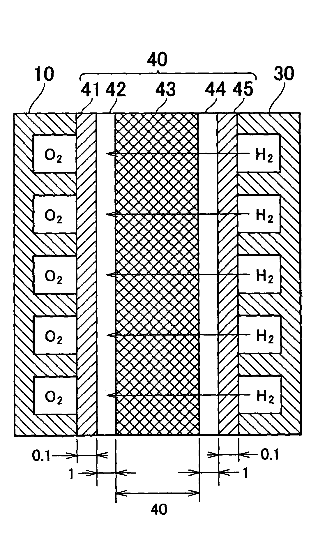
[0048]The electrolyte membrane 40 has a five-layer structure in which a dense substrate 43 formed from vanadium (V) is centrally disposed. Thin layers respectively constituted by electrolyte layers 42 and 44 that are made of a solid oxide are formed on both sides of the substrate 43. A barium-cerate-based (BaCeO3-based) ceramic proton conductor or a strontium-cerate-based (SrCeO3-based) ceramic proton conductor may be used as the material for the electrolyte layers 42 and 44. Coatings 41 and 45 of palladium (Pd) are provided on the outer surfaces of the electrolyte layers 42 and 44, respectively. In the second embodiment, the thickness of the coatings 41 and 45 of palladium (Pd) is set to be 0.1 μm. The thickness of the electrolyte layers 42 and 44 is set to be 1 μm. The thickness of the substrate 43 is set to be 40 μm. However, the thickness of each of the layers can be set as chosen. Moreover, instead of palladium (Pd), for example, vanadium (V), niobium (Nb), tantalum (Ta), an al...


PUM

PropertyMeasurementUnit
Thicknessaaaaaaaaaa
Permeabilityaaaaaaaaaa

Abstract

The invention provides an electrolyte membrane that allows an operating temperature of a solid polymer membrane fuel cell to be raised and an operating temperature of a solid oxide fuel cell to be lowered. This electrolyte membrane can be used in a fuel cell that is operable in an intermediate temperature range. The invention also provides a fuel cell using such an electrolyte membrane. The electrolyte membrane has a hydrated electrolyte layer, and dense layers made of a hydrogen permeable material that are formed on both sides of this electrolyte layer. Both sides of the electrolyte membrane are coated with dense layers. Consequently, evaporation of moisture contained in the electrolyte layer is suppressed, and increase in the resistance of the membrane is inhibited. As a result, the range of the operating temperature of the fuel cell can be enlarged.

Description

INCORPORATION BY REFERENCE[0001]The disclosure of Japanese Patent Application No. 2002-248054 filed on Aug. 28, 2002 and No. 2003-072994 filed on Mar. 18, 2003, including the specification, drawings and abstract is incorporated herein by reference in its entirety.BACKGROUND OF THE INVENTION[0002]1. Field of the Invention[0003]The invention relates to a solid electrolyte membrane for a fuel cell that is operable in a medium temperature range, a fuel cell using this solid electrolyte membrane, and manufacturing methods therefor.[0004]2. Description of Related Art[0005]In recent years, fuel cells for generating electric power by an electrochemical reaction between hydrogen and oxygen have attracted attention as an energy source. Amongst fuel cells, fuel cells using solid electrolyte membranes include low temperature fuel cells, such as solid polymer membrane fuel cells, and high temperature fuel cells such as solid oxide fuel cells.[0006]The solid polymer membrane fuel cell uses a poly...

Claims


Application Information

Patent Timeline
IPC IPC(8): H01M8/10H01B1/06H01M8/02H01M8/12
CPCH01M8/0291H01M8/1004H01M8/1213H01M8/124H01M8/1016Y02E60/521Y02E60/525H01M8/0289Y02E60/50Y02P70/50
Inventor ITO, NAOKIIIJIMA, MASAHIKOAOYAMA, SATOSHIIGUCHI, SATOSHINUMATA, KOICHI
Owner TOYOTA JIDOSHA KK
Why Eureka
Try Eureka