
Method and arrangement for generating an atmospheric pressure glow discharge plasma (APG)

a plasma and glow discharge technology, applied in the direction of plasma technique, chemical vapor deposition coating, coating, etc., can solve the problems of difficult to meet the criteria, unstable plasma at atmospheric pressure, and difficult to generate plasma under the above circumstances, and achieve outstanding surface treatment capabilities and cost-effective effects

Inactive Publication Date: 2009-02-17
FUJI PHOTO FILM BV
View PDF12 Cites 14 Cited by
  • Summary
  • Abstract
  • Description
  • Claims
  • Application Information

AI Technical Summary

Benefits of technology

"The present invention provides a cost-effective method for generating a stable and uniform low-temperature atmospheric pressure glow discharge plasma (APGD) with excellent surface treatment capabilities. The method involves using an AC-voltage at a frequency of at least 50 kHz and an electrodes arrangement with multiple electrodes. A gaseous substance is provided in the discharge space and an AC-voltage is applied to the electrodes with an amplitude equal to at least the breakdown voltage of the gas. The gas is kept at a temperature lower than 100°C to control the temperature in the discharge space. The method has several technical effects, including reducing energy dissipation, improving plasma stability and uniformity, and reducing the minimum exposure time. The method can be used in various industrial processes involving thermoplastic polymers. The use of air, nitrogen, or argon as the gaseous substance is preferred. The concentration of the gas can be increased stepwise to achieve a stable plasma."

Problems solved by technology

Generating a plasma under the above circumstances is not a straightforward technique.
Plasmas at atmospheric pressures are very unstable and will tend to go into a spark or an arc in short time after the breakdown.
It is important to note that for streamer discharges, like a corona or a silent discharge, it is very difficult to meet the criteria mentioned above.
As a result, this type of discharge can not cover all the material to be treated and gaps of a few millimeters exist between the streamer discharges.
The document however suggests that for higher frequencies the plasma becomes unstable and cannot be sustained anymore.
These temperatures however make this plasma unsuitable for surface treatment of temperature sensitive substrates, such as thermoplastic polymer films.
The application of helium however in methods for generating APG plasmas at high frequency (>50 kHz) of the AC-voltage, is not favourable.
Helium is an expensive gas due to the fact that it is rare and difficult to extract.

Method used


Image

  • Method and arrangement for generating an atmospheric pressure glow discharge plasma (APG)
  • Method and arrangement for generating an atmospheric pressure glow discharge plasma (APG)
  • Method and arrangement for generating an atmospheric pressure glow discharge plasma (APG)

Examples


example 2

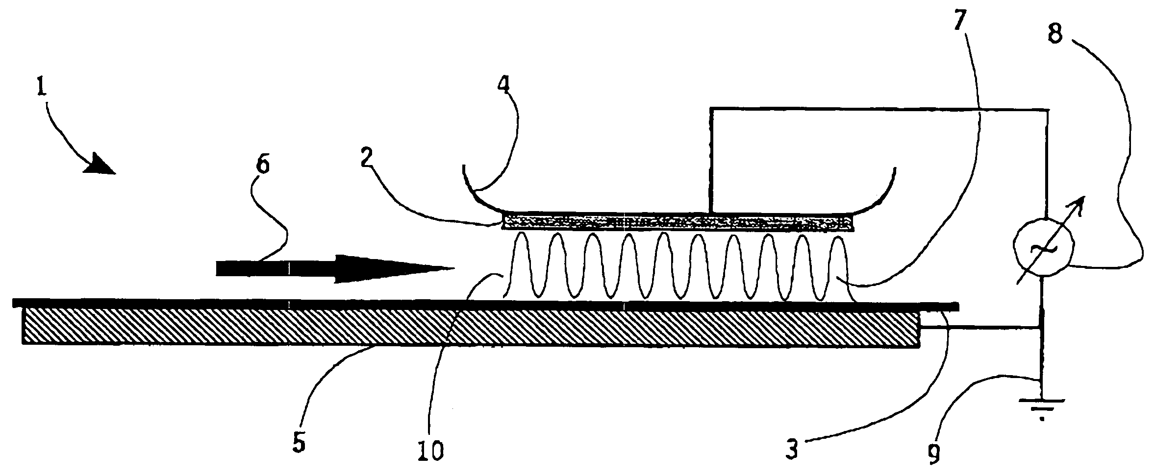
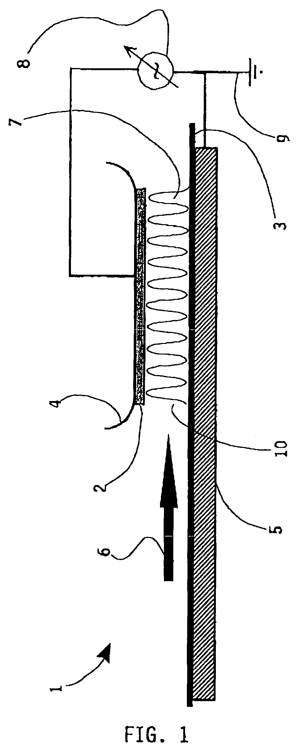
[0104]In a second example, an atmospheric pressure glow discharge plasma was generated by applying nitrogen gas (N2) with a velocity of 2 m / s into the discharge space at an amplitude of the applied voltage of 4.5 kV. Both electrodes are covered with a dielectric material comprising of polyethylenenaphtalate (PEN) and having a thickness of 100 μm. The gap distance between the electrodes (typically forming the discharge space) is 1 mm. An LC matching network is incorporated in the plasma arrangement. The results of the measurements are listed in the table below and are presented in the graph in FIG. 4. Again the power P coupled into the APG plasma 28, the exposure non-uniformity parameter δD 29 and the minimum time of exposure tminim 30 are shown.

[0105]

f [kHz]P [W]δD [%]tminim [s]12942394630452836707818228222076

example 3

[0106]In a third example, an atmospheric pressure glow discharge plasma was generated by applying air with a velocity of 2 m / s into the discharge space at an amplitude of the applied voltage of 4.5 kV. Both electrodes are covered with a dielectric material comprising of polyethylenenaphtalate (PEN) and having a thickness of 100 μm. The gap distance between the electrodes (typically forming the discharge space) is 1 mm. An LC matching network is incorporated in the plasma arrangement. The results of the measurements are listed in the table below and are presented in FIG. 5. Again the power P coupled into the APG plasma 31, the exposure non-uniformity parameter δD 32 and the minimum time of exposure tminim 33 are shown.

[0107]

f [kHz]P [W]δD [%]tminim [s]129462906330521201357089705282290209

example 4

[0108]As an example of a measurement at a frequency of approximately 280 kHz, FIG. 6 presents a diagram of the AC-voltage applied to the electrodes and the plasma current of a plasma generated using a method or arrangement according to the present invention. In this particular example, the carrier gas used was argon at a flow velocity of 2 m / s, the gap distance was 2 mm. The plasma current is shown by the solid line and the applied voltage by the dotted line.

[0109]The results of the above-mentioned experiments show a stable APG plasma can be generated in the presence of argon, nitrogen and air at high frequency. However the operation window for maintaining a uniform and stable plasma for the nitrogen and air gasses are rather limited. For argon gas said phenomena is surprisingly not observed. On the other hand, it is observed that at frequency ranges between 200 to 500 kHz, the plasma non-uniformity of the gasses are one order of magnitude smaller than those obtained in the frequenc...


PUM

PropertyMeasurementUnit
frequencyaaaaaaaaaa
frequencyaaaaaaaaaa
frequencyaaaaaaaaaa

Abstract

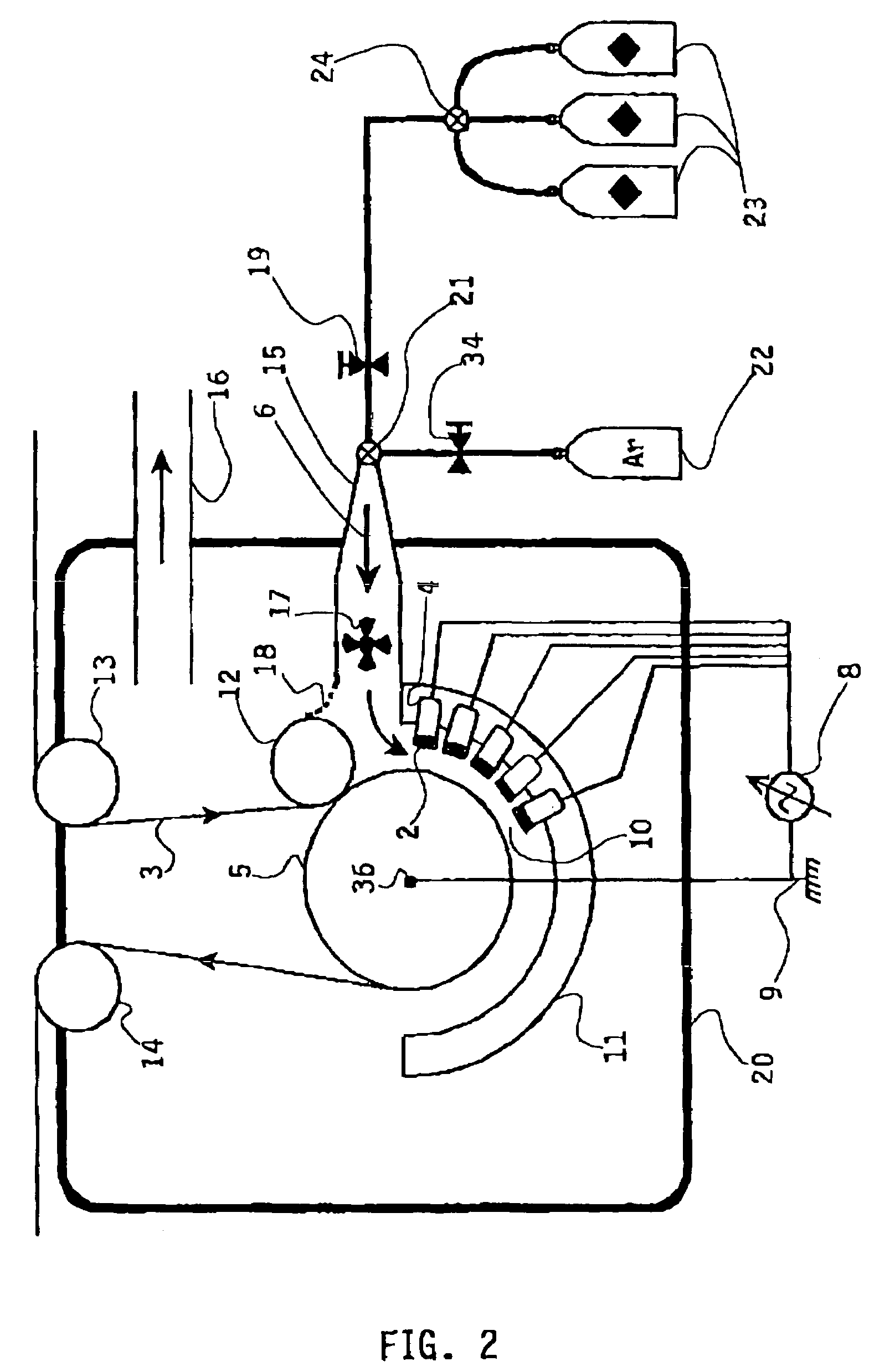
Method and arrangement (1) for generating an atmospheric pressure glow plasma APG (7), where in a plurality of electrodes, (4, 5) are arranged defining a discharge space (10) for forming said plasma (7). The electrodes (4,5) are connected to a power supply (8) providing an AC-voltage having a frequency of at least 50 kHz to the electrodes (4,5). A gaseous substance (6) is provided in said discharge space and comprises t least one of a group of argon, nitrogen and air.

Description

[0001]This application claims priority to European Patent Application No. 02079074.7, filed Sep. 30, 2002, and PCT Patent Application No. PCT / EP2003 / 010923, filed Sep. 30, 2003 which are incorporated by reference herein.FIELD OF THE INVENTION[0002]The present invention generally relates to a method and apparatus for generating atmospheric pressure glow discharge (APG) plasma and the use thereof. In particular it is related to a method and apparatus for generating an atmospheric glow discharge plasma (APG), wherein a plurality of electrodes are arranged defining a discharge space for forming said plasma.BACKGROUND OF THE INVENTION[0003]Modification or treatment of a surface by applying glow plasma is a known technique in industries, such as photo film production industry, used in order to improve certain surface and material properties. For instance, in the production of photo film, a thermoplastic polymer film (triacetyl cellulose (TAC), polyethyleneterephthalate (PET), polyethylene...

Claims


Application Information

Patent Timeline
Patent Type & Authority Patents(United States)
IPC IPC(8): H05H1/24B05D3/14B05D7/24C23C16/503C23C16/505H01J37/32H05H1/46
CPCC23C16/503C23C16/505H01J37/32036H01J37/32082H01J37/32825H05H1/24B05D1/62B05D3/141B05D2252/02H05H1/2431
Inventor DE VRIES, HINDRIK WILLEMMORI, FUYUHIKOALDEA, EUGENVAN DE SANDEN, MAURITIUS CORNELIUS MARIA
Owner FUJI PHOTO FILM BV
Learn More