
Method and apparatus for selective blocking of radio frequency identification devices

a radio frequency identification and selective blocking technology, applied in the field of radio frequency identification (rfid) tags, can solve the problems of unworkable simple measures like kill commands, unsatisfactory privacy enforcement, and potential widespread threat to consumer privacy, and achieve the effect of enhancing consumer privacy, cost-effectiveness, and reducing the effectiveness of the device as a tracking mechanism

Active Publication Date: 2005-11-29
EMC IP HLDG CO LLC
View PDF3 Cites 317 Cited by
  • Summary
  • Abstract
  • Description
  • Claims
  • Application Information

AI Technical Summary

Benefits of technology

[0014]Advantageously, an RFID device or other blocker device configured to include a selective blocking feature in accordance with the invention provides enhanced consumer privacy, without significantly undermining the effectiveness of the device as a tracking mechanism prior to consumer possession thereof. Moreover, such protection is provided in a particularly cost-effective manner, without significantly increasing the complexity of the RFID devices or the device reader.

Problems solved by technology

The impending ubiquity of RFID tags, however, also poses a potentially widespread threat to consumer privacy.
There are many environments, however, in which simple measures like kill commands are unworkable or undesirable for privacy enforcement.
RFID tags will inevitably see use, however, in a vast range of objects, including clothing and wristwatches, that cannot be placed conveniently in containers.
This crude approach raises legal issues relating to broadcast power levels, and could cause severe disruption of all nearby RFID systems, even those in legitimate applications where privacy is not a concern.
However, the severe cost constraints on basic RFID tags may preclude implementation of such tag-based cryptographic functionality in practical applications.
However, these re-encryption techniques require significant computational infrastructure external to the tags, and are thus likely to be unduly burdensome in practice.

Method used


Image

  • Method and apparatus for selective blocking of radio frequency identification devices
  • Method and apparatus for selective blocking of radio frequency identification devices
  • Method and apparatus for selective blocking of radio frequency identification devices

Examples


example 1

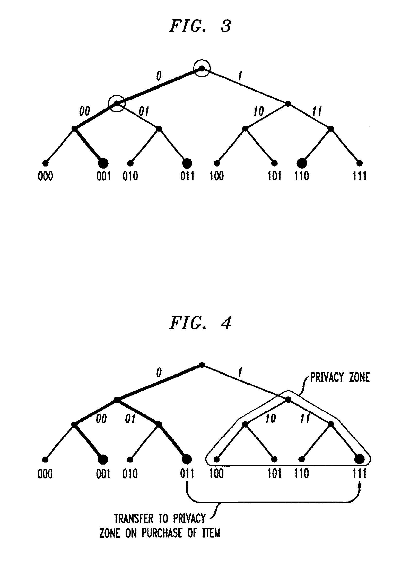
[0082]Privateway Supermarkets makes use of selective blocker tags whose privacy zone consists of all IDs with a leading ‘1’ bit. Packages in Privateway Supermarkets each bear an RFID tag with a unique ID used for purposes of inventory control. As initially programmed, and while an item is inside the supermarket or its warehouses, the tag ID carries a leading ‘0’ bit. At this point, the selective blocker tags do not disrupt the ordinary reading of other tags.

[0083]When the RFID tag reader at a cash register scans an item for purchase by a customer, it also transmits a tag-specific key to the RFID tag on the item, causing the leading bit in the tag ID to flip to a ‘1’. The key should be secret so as to prevent an attacker from transferring tag IDs arbitrarily into the privacy zone. Privateway Supermarkets also provides its customers with free selective blocker tags. These may be available, for example, embedded in shopping bags at registers, as stickers to be placed on items, or using...

example 2

[0089]Suppose that the first two bits of tag IDs specify a desired privacy zone ranging from zero to three. Alice might carry a zone-one selective blocker tag in her wristwatch. So as to protect her clothing and personal appliances from scrutiny, all of these items would then be marked with a zone-one prefix.

[0090]On the other hand, Alice might like to be able to handle groceries without blocking their tags. In this case, on checkout, her grocery items could be marked with a zone-two prefix, while privacy stickers for these items carry zone-two selective blocker tags. Thus, when the stickers are removed, Alice can handle them without her wristwatch blocker tag interfering with the reading process. Alice might choose, on the other hand, for her automobile to implement the strongest level of protection, blocking RFID tag reading in all four zones.

example 3

[0091]As indicated previously, proposals have been made to embed RFID tags in currency. Using the techniques of the invention, IDs for these tags might be relegated to a special privacy zone for currency.

[0092]To protect the privacy of consumers, then, wallets could be equipped with embedded selective blocker tags or with credit-card-like devices bearing selective blocker tags.

[0093]The presence of a currency-zone blocker tag would be easily detectable, as will be described below. Thus, in sensitive locations like airports, law-enforcement officials could take the approach of temporarily sequestering wallets in Faraday cages during security checks. They could then detect the presence of suspicious currency-zone blocker tags. In the absence of such tags, or following their identification and removal, it would be possible to monitor large and suspicious currency flows. The particular policies are obviously a subject for debate. However, the selective blocker tags of the present invent...


PUM


Abstract

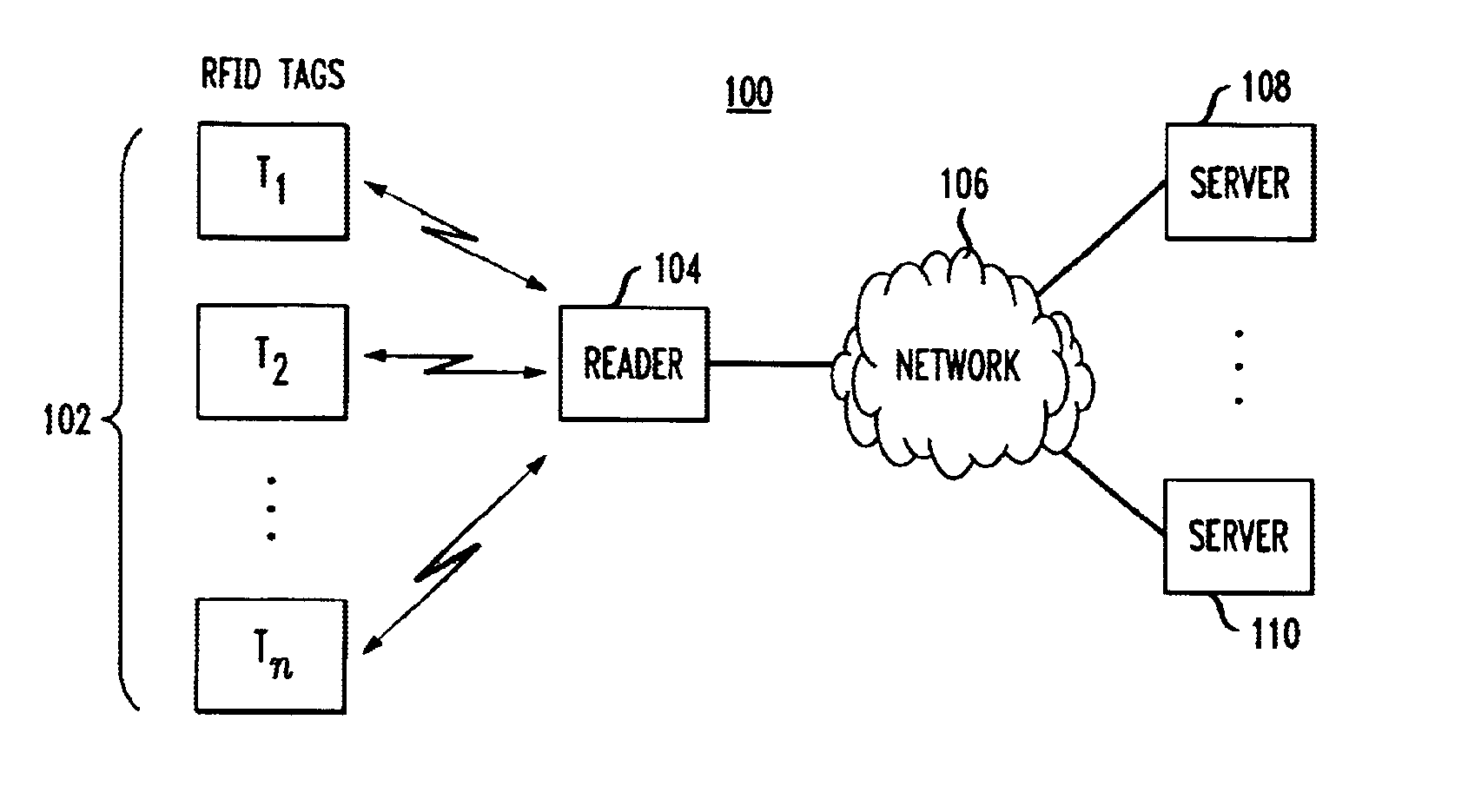
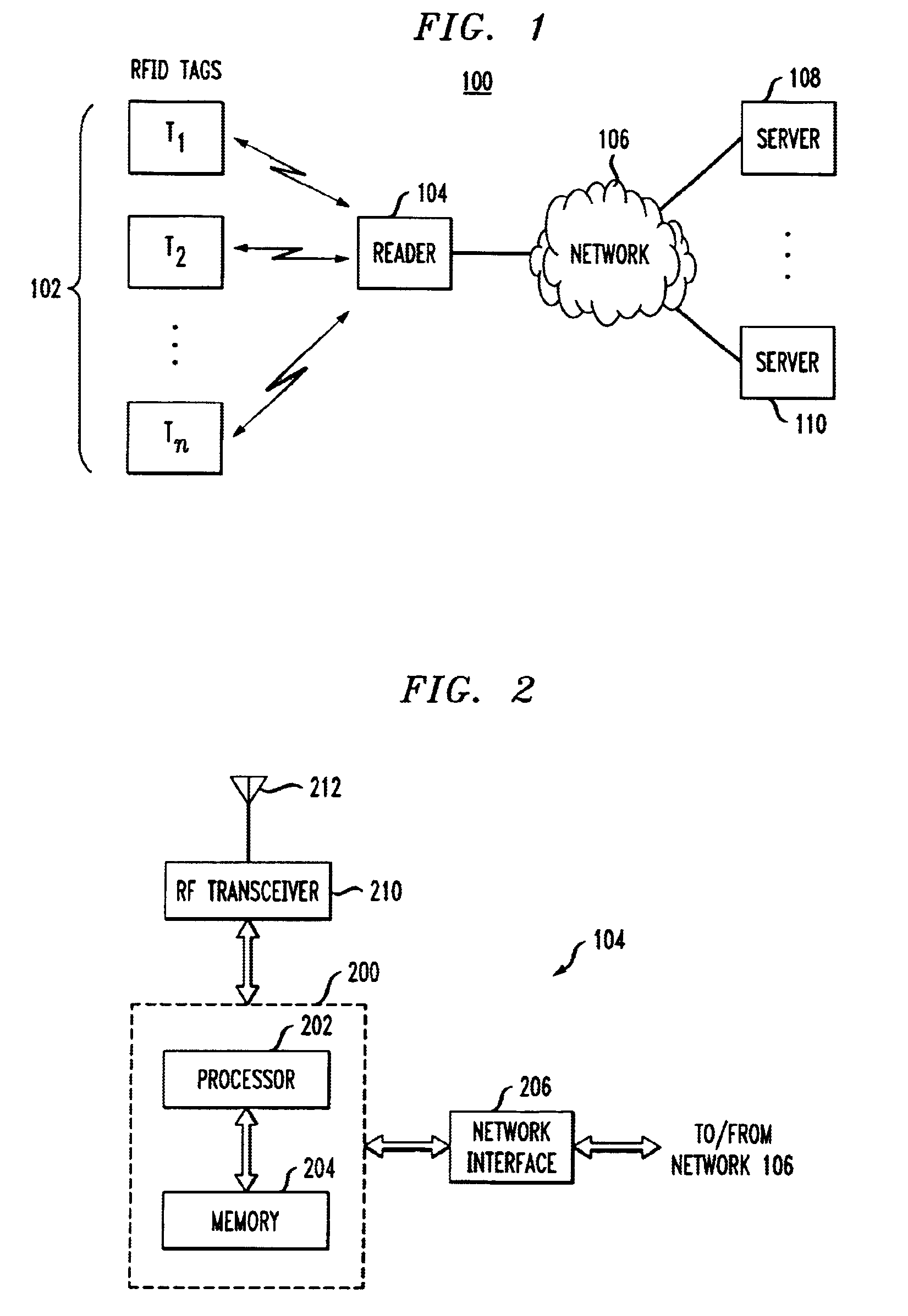
Techniques are disclosed for providing enhanced privacy in an RFID system comprising a plurality of RFID devices, each having an associated identifier, and at least one reader which communicates with one or more of the devices. A blocker device is operative to receive a communication directed from the reader to one or more of the RFID devices, and to generate, possibly based on information in the received communication, an output transmittable to the reader. The output simulates one or more responses from at least one of the RFID devices in a manner which prevents the reader from determining at least a portion of the identifier of at least one of the RFID devices. The blocker device may itself comprise one of the RFID devices. In an illustrative embodiment, the output generated by the blocker device interferes with the normal operation of a singulation algorithm implemented by the reader.

Description

RELATED APPLICATIONS(S)[0001]The present application claims the priority of U.S. Provisional Patent Application Ser. No. 60 / 468,750, filed May 8, 2003 and entitled “The Wildcard-Tag: Selective Jamming for Consumer Privacy,” and U.S. Provisional Patent Application Ser. No. 60 / 471,187, filed May 16, 2003 and entitled “The Blocker Tag: Selective Blocking of RFID Tags for Consumer Privacy,” the disclosures of which are incorporated by reference herein.FIELD OF THE INVENTION[0002]The present invention relates generally to radio frequency identification (RFID) tags or other types of RFID devices, and more particularly to techniques for providing enhanced privacy in conjunction with the use of such devices.BACKGROUND OF THE INVENTION[0003]A conventional RFID tag typically comprises an integrated circuit transceiver capable of transmitting a unique serial number or other identifying information to a nearby reader in response to a query from the reader. Many RFID tags are “passive” in that t...

Claims


Application Information

Patent Timeline
Patent Type & Authority Patents(United States)
IPC IPC(8): G06K19/07
CPCG06K7/0008G06K19/0723G06K19/07336
Inventor JUELS, ARIRIVEST, RONALD L.SZYDLO, MICHAEL
Owner EMC IP HLDG CO LLC
Learn More