System and process for non-invasive collection and analysis of physiological signals
a physiological signal and non-invasive technology, applied in the field of non-invasive analysis of physiological signals, can solve the problems of difficult to distinguish different events that can occur throughout the night, lack of substantial improvement to correct problems, and the type of sensor, etc., to achieve the effect of improving signal processing, increasing efficiency, and increasing efficiency without adding exorbitant costs
- Summary
- Abstract
- Description
- Claims
- Application Information
AI Technical Summary
Benefits of technology
Problems solved by technology
Method used
Image
Examples
first embodiment
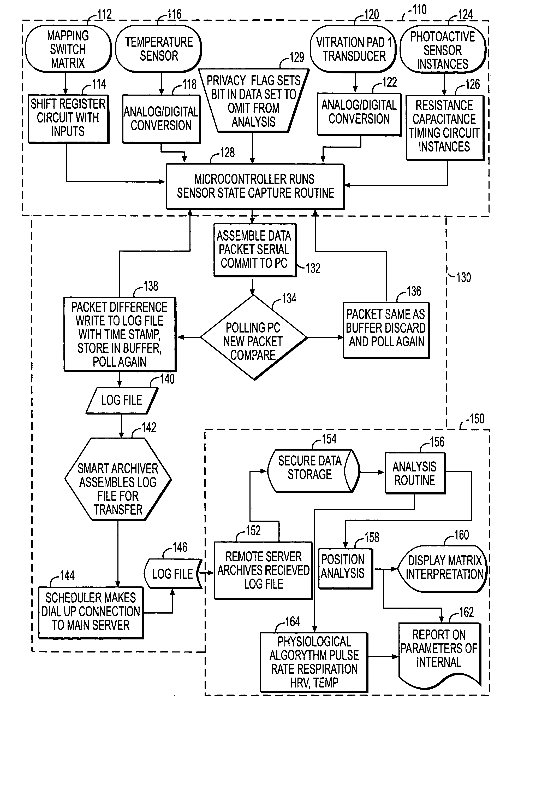
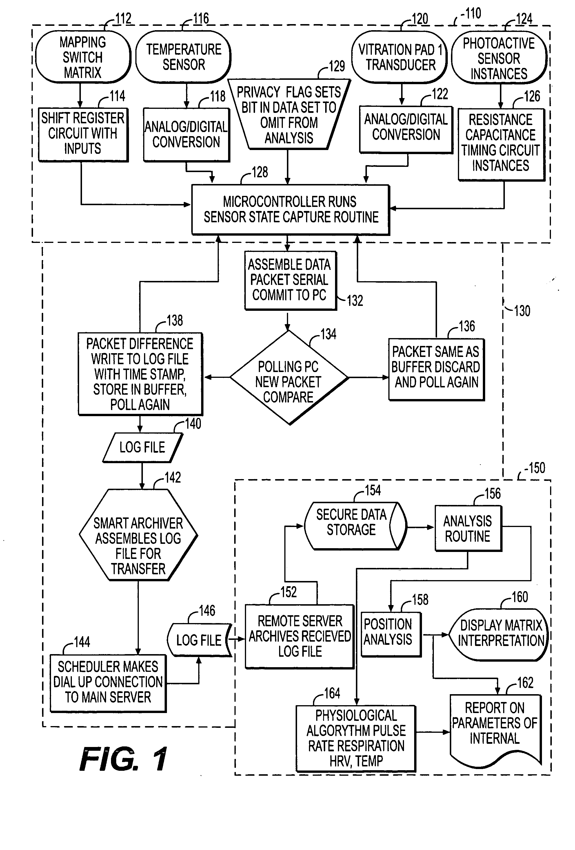
[0035]FIG. 1 is a flow chart schematically illustrating a non-invasive data acquisition and processing system constructed according to the principles of the invention. While the data flow is described in a particular manner, it is understood that the data may flow and be processing in a variety of configurations, as recognized by skilled artisans. Generally, the flowchart may be broken into three circuitry sections: a module for data acquisition 110; a module for arranging data 130; and, a module for analyzing data 150.
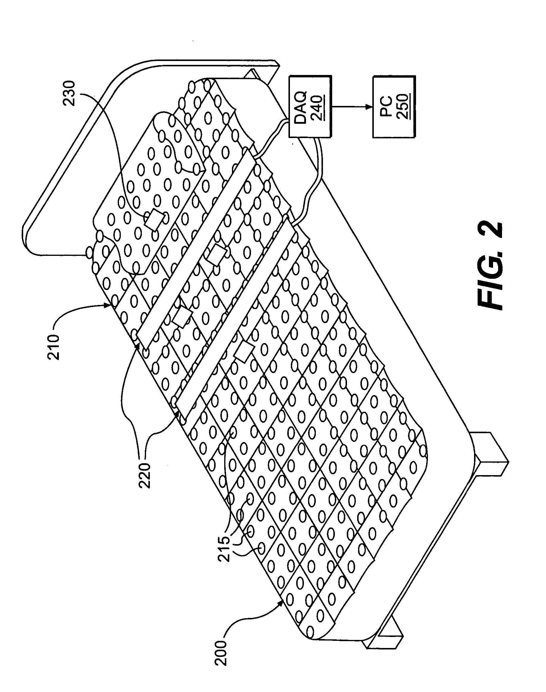
[0036] Inputs from the suite of sensors detecting physiological conditions of a subject form part of the data acquisition module 110. Data acquisition module 110 includes a mapping switch matrix 112 that provides data to a shift register at 114. Data from the mapping switch matrix 112 includes data based on the position of the subject on a mattress, described in more detail below with reference to FIG. 2, or other support. The shift register 114 outputs the positional...
second embodiment
[0067]FIG. 9 illustrates an amplifier and filter circuit constructed according to principles of the invention that may be used to process physiological signals obtained from a vibration sensor. A sensor 905 is connected to an instrumentation amplifier 910. The sensor 905 may be, for example, a pressure sensor. The output signal from the instrumentation amplifier 910 is fed into a second order band pass filter 920 and into a second order low pass filter 930. The output signal from the second order band pass filter 920 is fed into a first inverting amplifier 950. The output signal from the first inverting amplifier 950 has a bias voltage 960 applied, and the resulting signal is fed into a first low pass passive filter 970. The output signal from the first low pass passive filter 970 results in a waveform corresponding to the chest movement of the subject. By way of example, the waveform corresponding to the chest movement may be in a range of between about 0.025 and about 0.515 Hz.
[00...
third embodiment
[0071]FIG. 10 illustrates an amplifier and filter circuit constructed according to principles of the invention that may be used to process physiological signals obtained from a vibration sensor. The circuit 1000 may be used within a process and system of the invention to process physiological signals obtained from a sensor of the invention such as a vibration sensor shown at 120. An ultra-sensitive vibration (such as a piezoelectric, fiber optic or load cell based) sensor may be used that, through the signal processing techniques in the circuit 1000, can provide waveforms indicative of both heart rate and breathing rate. Circuit 1000 may be provided in an analysis routine, such as in analysis 156.
[0072] In the example of circuit 1000, the raw signal from the vibration transducer sensor 1005 (which can be replaced with other types of sensors) is sent through a series of amplifiers and filters to separate the signal into useable waveforms. At the first stage 1010, which amplifies the ...
PUM
 Abstract
Description
Claims
Application Information
 - R&D
- Intellectual Property
- Life Sciences
- Materials
- Tech Scout
- Unparalleled Data Quality
- Higher Quality Content
- 60% Fewer Hallucinations
Browse by: Latest US Patents, China's latest patents, Technical Efficacy Thesaurus, Application Domain, Technology Topic, Popular Technical Reports.
© 2025 PatSnap. All rights reserved.Legal|Privacy policy|Modern Slavery Act Transparency Statement|Sitemap|About US| Contact US: help@patsnap.com


