
Two-stage laser pulse energy control device and two-stage laser system

a laser system and laser pulse technology, applied in the direction of instruments, photomechanical equipment, active medium materials, etc., can solve the problems of difficult to ensure the desired pulse energy, the high-precision pulse energy control means used at the time of the burst operation has not been established for the two-stage laser, etc., and achieves high throughput of the exposure device and resolution high

Active Publication Date: 2008-06-03
GIGAPHOTON
View PDF2 Cites 10 Cited by
  • Summary
  • Abstract
  • Description
  • Claims
  • Application Information

AI Technical Summary

Benefits of technology

[0092]According to the first invention, the pulse energy of the two-stage laser can be controlled. Therefore, the pulse energy of the two-stage laser can be stabilized.
[0093]According to the first invention, the oscillating laser and the amplifying laser can be controlled apparently separately, so that the control can be made stably, and an error does not occur readily. Therefore, the accuracy of the control can be improved.
[0094]According to the second through fourth inventions, the same effects as those obtained by the first invention can be obtained.
[0095]Especially, according to the second through fourth inventions, the oscillating laser can be controlled by simply controlling the pulse energy of the seed light to the above-described Es0 or more (e.g., a charging voltage of the oscillating laser is kept constant), and it is not necessary to control the pulse energy with high accuracy. Substantially, the amplifying laser is just controlled strictly. The pulse energy Pamp after the amplification is measured, and according to the measured result, the charging voltage Vamp of the amplifying laser is controlled for every pulse, thereby enabling to control the pulse energy of the amplified laser beam with high accuracy.
[0096]When the control includes simple control and strict control as in the second through fourth inventions, the control is easy, so that a computation load of the controller is low. Therefore, a high-performance controller is not needed, and the cost can be reduced.
[0097]And, joint use of the control to vary a gas pressure and a gas composition of the oscillating laser and the control to vary them of the amplifying laser enables to make pulse energy control for compensating a medium-term (during the gas life) and long-term (laser chamber's life length) output drop, and it becomes possible to control the pulse energy stably for a long period.

Problems solved by technology

But, a high-precision pulse energy control means used at the time of the burst operation has not been established for the two-stage laser.
Therefore, it is hard to ensure the desired pulse energy.

Method used


Image

  • Two-stage laser pulse energy control device and two-stage laser system
  • Two-stage laser pulse energy control device and two-stage laser system
  • Two-stage laser pulse energy control device and two-stage laser system

Examples


Embodiment Construction

[0107]Embodiments of the present invention will be described with reference to the drawings.

Structure

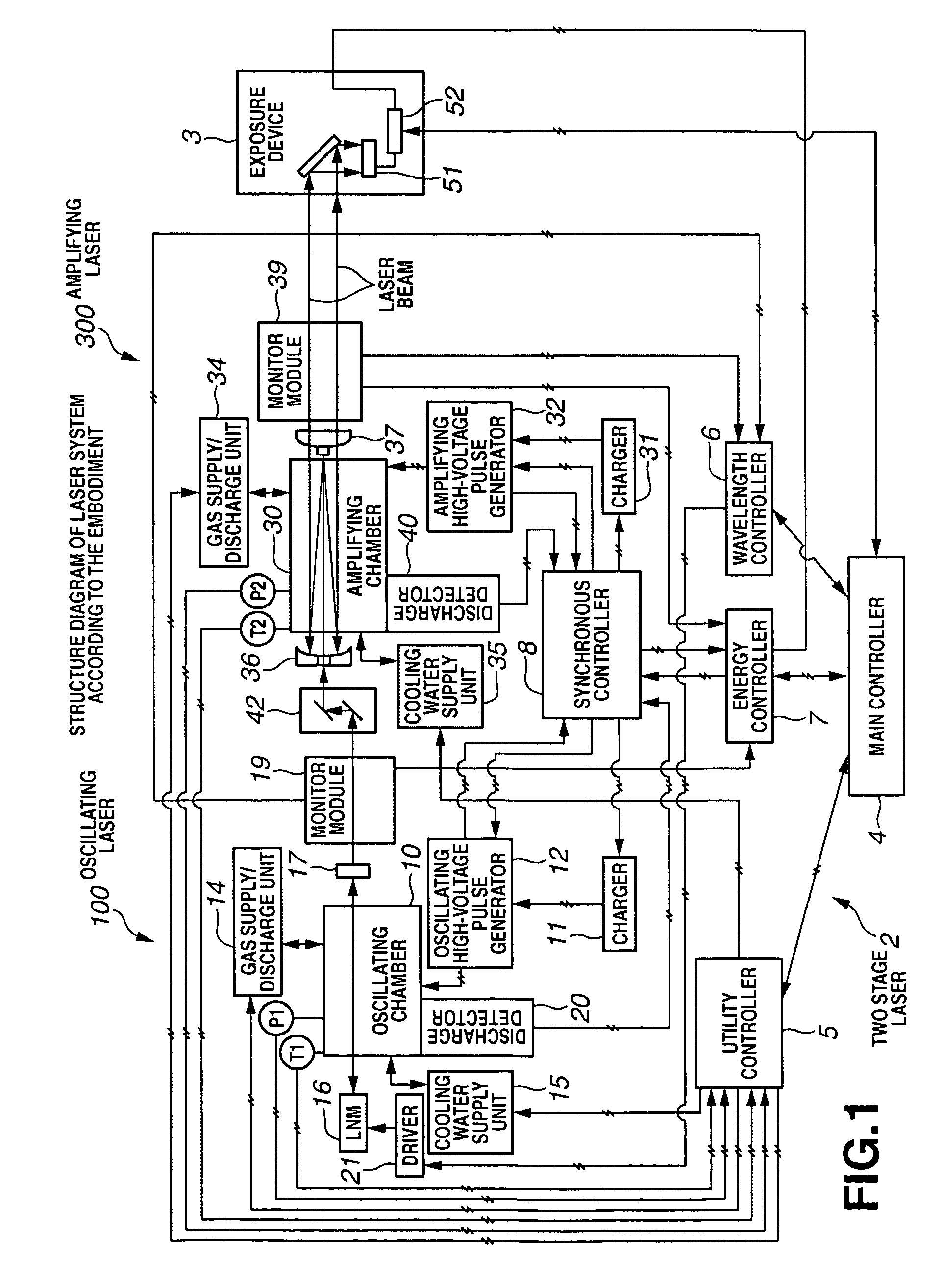
[0108]FIG. 1 is a structure diagram of the laser system according to this embodiment. And, FIG. 2A is a structure diagram of an oscillating chamber and its vicinity, and FIG. 2B is a structure diagram of an amplifying chamber and its vicinity. FIG. 1 shows the two-stage laser apparatus of an MOPO system.

[0109]In a two-stage laser apparatus 2, seed light (seed laser beam) is produced and narrow-banded by an oscillating laser (osc) 100. And, the seed light is amplified by an amplifying laser (amp) 300. Specifically, spectral characteristics of laser system as a whole depend on the spectral characteristics of the laser beam output from the oscillating laser 100, and the laser output (energy or power) of the laser system itself depends on the amplifying laser 300. The laser beam output from the amplifying laser 300 is input to an exposure device 3, and this laser beam is used to expose a...


PUM

PropertyMeasurementUnit
repetition frequencyaaaaaaaaaa
Full Width at Half Maximumaaaaaaaaaa
pulse energy Poscaaaaaaaaaa

Abstract

A charging voltage Vosc applied to a main capacitor C0 disposed in an oscillating high-voltage pulse generator 12 of an oscillating laser 100 is subject to constant control such that a pulse energy Posc of the oscillating laser 100 becomes a lower limit energy Es0 or more of an amplification saturation region. And, a charging voltage Vamp applied to a main capacitor C0 disposed in an amplifying high-voltage pulse generator 32 of an amplifying laser 300 is controlled, and pulse energy Pamp of the amplifying laser 300 is determined as target energy Patgt. Thus, the pulse energy of a two-stage laser is controlled to stabilize the pulse energy.

Description

TECHNICAL FIELD[0001]The present invention relates to a two-stage laser pulse energy control device provided with an optical oscillation stage that outputs seed light and an optical amplification stage into which the seed light is injected and that amplifies and outputs an energy of the seed light, and also relates to a two-stage laser system provided with the two-stage laser pulse energy control device and an exposure device.BACKGROUND ART[0002]In recent years, an excimer laser apparatus and a molecular fluorine laser apparatus are taken into consideration and adopted as a lithography light source. In such a case, the following two points are required in order to improve the throughput of an exposure device and to conduct ultrafine fabrication uniformly.[0003]A first point is to provide a high power laser beam. To provide high power, there is a method of increasing a pulse energy per pulse of a laser pulse which is output from a laser apparatus. And, if the pulse energy per pulse i...

Claims


Application Information

Patent Timeline
Patent Type & Authority Patents(United States)
IPC IPC(8): H01S3/22H01S3/223G03F7/20H01L21/027H01S3/097H01S3/10H01S3/134H01S3/23
CPCG03F7/70041H01S3/097H01S3/1301H01S3/09702H01S3/10007H01S3/104H01S3/134
Inventor ARIGA, TATSUYAWAKABAYASHI, OSAMUKAKIZAKI, KOUJI
Owner GIGAPHOTON
Learn More