
High performance piezoelectric actuator

a piezoelectric actuator, high-performance technology, applied in the direction of piezoelectric/electrostrictive/magnetostrictive devices, piezoelectric/electrostrictive/magnetostriction machines, piezoelectric/electrostrictive/magnetostriction devices, etc., can solve the problems of undetectable rough surfaces, weakening the piezoelectric materials, and problematic surface defects of conventional piezoelectric ceramics. achieve high coup

Inactive Publication Date: 2008-05-06
RGT UNIV OF CALIFORNIA
View PDF7 Cites 33 Cited by
  • Summary
  • Abstract
  • Description
  • Claims
  • Application Information

AI Technical Summary

Benefits of technology

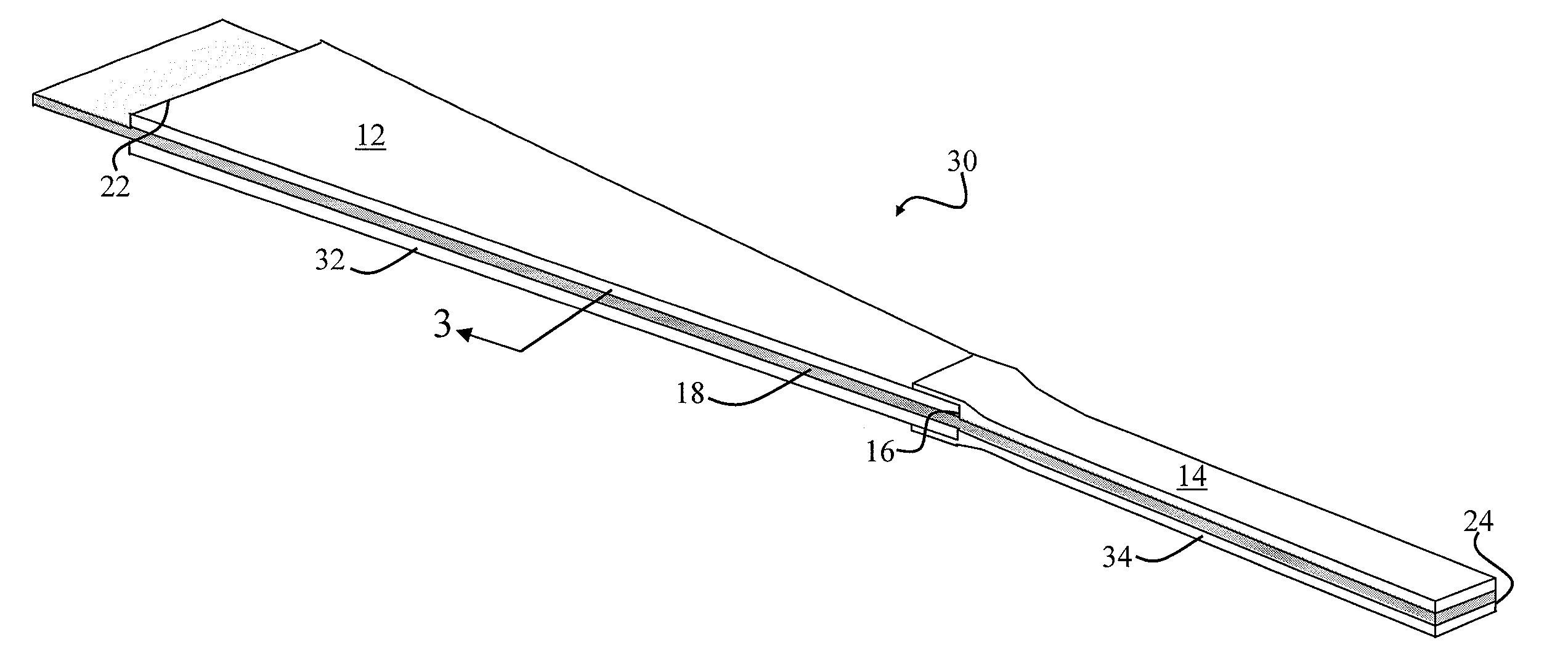
The present invention provides a piezoelectric actuator with a tapered width and a passive material integrated with the piezoelectric material. The actuator includes a drive system capable of selectively applying an electric field to the piezoelectric material. The piezoelectric material exhibits a default state of compression along its surface. The actuator further includes a rigid extension that is positioned at one end of the piezoelectric layer, which exhibits a tapered width. The passive layer includes ultra-high modulus materials, which act as an electrode to facilitate driving the actuator. The mismatched coefficients of thermal expansion between the piezoelectric and passive layers help to improve actuator fracture load capabilities. The invention enables high performance actuators that perform close to the strain energy density limits for a bulk free piezoelectric material and allows for the use of high stress applications.

Problems solved by technology

Unfortunately, conventional piezoelectric ceramics exhibit problematic surface defects resulting from ceramic crystal growth and subsequent processing.
Both cutting methods yield undesirably rough surfaces with relatively large cracks that weaken the piezoelectric materials.
Inherent surface and edge defects in conventional ceramic piezoelectric materials often significantly reduce actuator fracture toughness and fatigue life.
Furthermore, such defects cause material stress concentrations, which limit usable working stress range and thereby lower actuator energy density, i.e., work-performing capability per unit mass.
However, conventional polishing techniques may yield a surface layer of incomplete grains that may actually weaken the piezoelectric material.

Method used


Image

  • High performance piezoelectric actuator
  • High performance piezoelectric actuator
  • High performance piezoelectric actuator

Examples


first embodiment

[0014]FIG. 1 is a perspective view of a unimorph piezoelectric actuator according to the present invention.

second embodiment

[0015]FIG. 2 is a perspective view of a bimorph piezoelectric actuator according to the present invention.

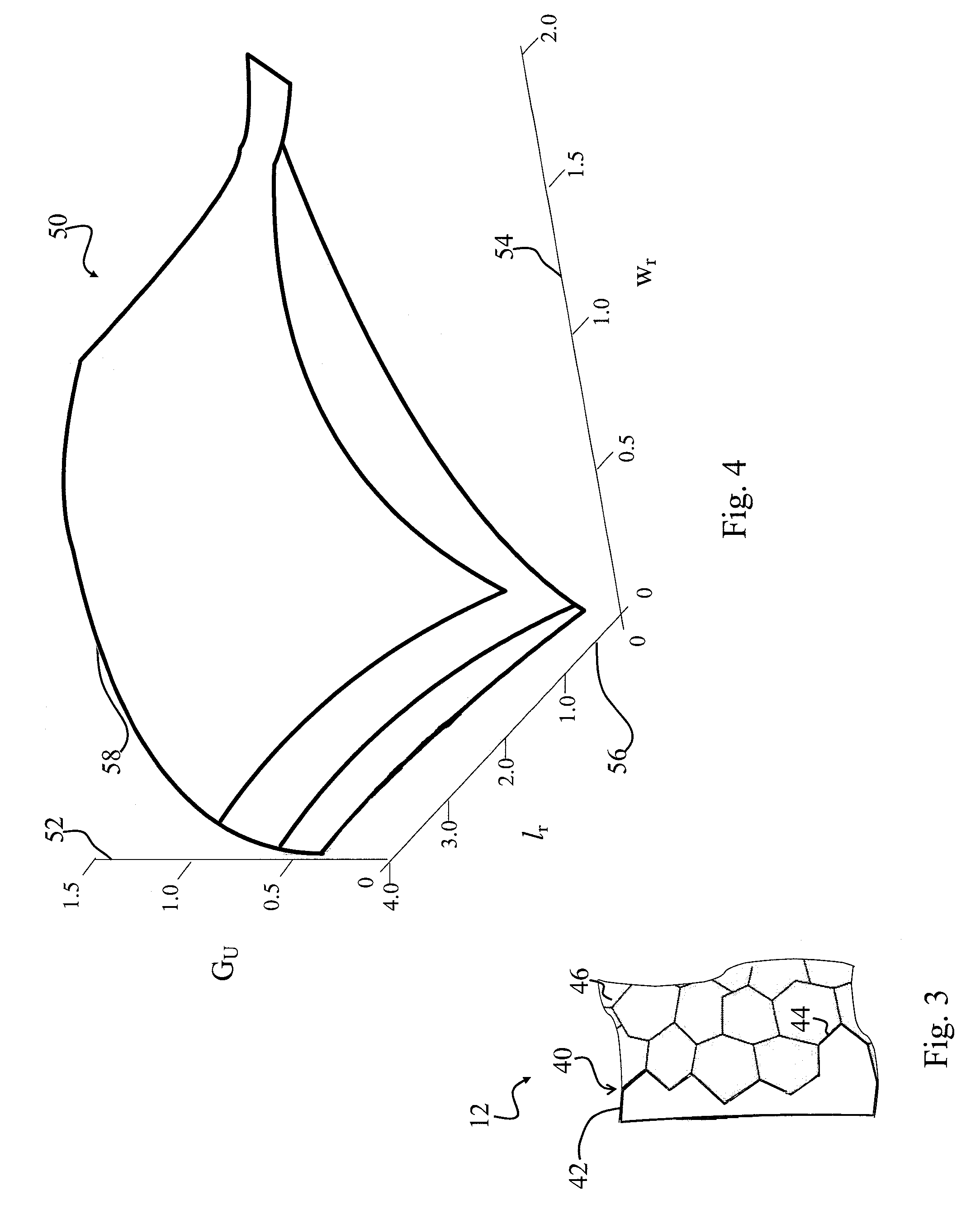
[0016]FIG. 3 is a sectional view of a piezoelectric surface with a compressive polymer coating employed by the actuators of FIGS. 1 and 2.

[0017]FIG. 4 is a graph illustrating actuator energy improvement as a function of the piezoelectric width ratio and the actuator extension ratio of the piezoelectric actuators of FIGS. 1 and 2.

[0018]FIG. 5 is a graph illustrating normalized strain versus normalized position along the piezoelectric actuators of FIGS. 1 and 2.

third embodiment

[0019]FIG. 6 is a perspective view of a curved unimorph actuator according to the present invention.

[0020]FIG. 7 is a vertical sectional view of a curved mold adapted to construct the unimorph piezoelectric actuator of FIG. 6.

[0021]FIG. 8 is a graph illustrating stress versus vertical position within the unimorph actuator of FIG. 6.

[0022]FIG. 9 is a schematic view of a drive system for driving the unimorph actuators of FIGS. 1 and 6.

[0023]FIG. 10 is a schematic view of an alternating drive system for driving the bimorph actuator of FIG. 2.

[0024]FIG. 11 is a schematic view of a simultaneous-drive system for driving the bimorph actuator of FIG. 2.


PUM


Abstract

A high performance piezoelectric actuator. The actuator includes a piezoelectric material exhibiting a selectively tapered width sufficient to enhance actuator fracture load capabilities. A passive material is disposed on or integrated with the piezoelectric material. A drive system is connected to the piezoelectric material. The drive system is capable of selectively applying an electric field to the piezoelectric material. In specific embodiment, the piezoelectric material includes a curved piezoelectric layer exhibits a default state of compression along a surface of the piezoelectric layer.

Description

ACKNOWLEDGMENT OF GOVERNMENT SUPPORT [0001]This invention was made with Government support under Grant (Contract) No. N00014-98-1-0671 awarded by ONR MURI. The Government has certain rights to this invention.[0002]This application claims the benefit of U.S. Provisional Patent Application 60 / 470,456 filed May 14, 2003 and fully incorporated herein by reference.BACKGROUND OF THE INVENTION[0003]This invention is related in general to actuators. More specifically, embodiments of the present invention relate to piezoelectric actuators.[0004]Piezoelectric actuators are employed in various demanding applications including robotic flying insects, miniature optical switches, inkjet printers, and micropumps. Such applications demand miniature actuators that can reliably produce relatively large displacements under high dynamic loads.[0005]Piezoelectric actuators are often constructed from dielectric ceramic single crystal or amorphous polycrystalline ceramics, which expand or contract in resp...

Claims


Application Information

Patent Timeline
Patent Type & Authority Patents(United States)
IPC IPC(8): H01L41/04H01L41/08H10N30/00H10N30/80
CPCH01L41/094H10N30/2042
Inventor WOOD, ROBERT J.FEARING, RONALD S.HICKERSON, JACOBY L.
Owner RGT UNIV OF CALIFORNIA
Learn More