Material and process for thermal coating, surface layer and also compressor with a surface layer of the material

a technology of thermal coating and surface layer, which is applied in the direction of efficient propulsion technology, climate sustainability, and engines without rotary main shafts, etc. it can solve the problems of contamination of system components by lubricating oil, material is however completely unsuitable for the case, and the compressor is prone to considerable problems. , to achieve the effect of improving toughness, improving hardness and good tribological characteristics

Active Publication Date: 2008-04-15
SULZER METRO AG
View PDF19 Cites 6 Cited by
  • Summary
  • Abstract
  • Description
  • Claims
  • Application Information

AI Technical Summary

Benefits of technology

[0021]An object of the present invention is thus to propose a new material and a process for the formation of a surface layer by means of thermal coating, with which in particular an improvement of the toughn

Problems solved by technology

Whereas the previously mentioned highly developed materials for the production of surface layers lead in the case of oil lubricated applications to excellent results in the technical application, these materials are however completely unsuited for the case in which the use of lubricants is to be avoided, since these materials were indeed specially developed for use in oil lubricated applications.
An important example for an application, which brings considerable disadvantages when using a lubricating liquid, is compressors for the compression of gases.
Irrespective of which special application or embodiment of the compressor is used, considerable problems exist with these oil lubricated compressors known from the prior art due to the contamination of the gases to be compressed by the lubricant.
For example, if high purity gases are required, for example for laboratory use, or if compressed gases are present which are to be burned in highly complicated components of combustion systems, contamination of the system components by lubricating oil can arise.
Thus, for example with vehicles operated with natural gas, components of the injection system such as the injection pump or the injection nozzles can be contaminated.
For reasons of environmental protection a contamination of the compressed gases is frequently also highly undesired because lubricant can for example enter into the environment as a finely distributed mist or can be burned at the same time, for example in a vehicle operated with natural gas, whereby noxious combustion products can arise.
In addition to contamination, which can lead to blockages or restrictions in fine high pressure lines amongst other things, problems arise not infrequently with enhanced corrosion, for example of components such as metallic high pressure lines, nozzles in the system

Method used


Image

  • Material and process for thermal coating, surface layer and also compressor with a surface layer of the material
  • Material and process for thermal coating, surface layer and also compressor with a surface layer of the material

Examples


Embodiment Construction

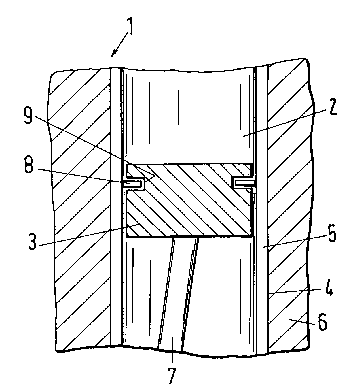
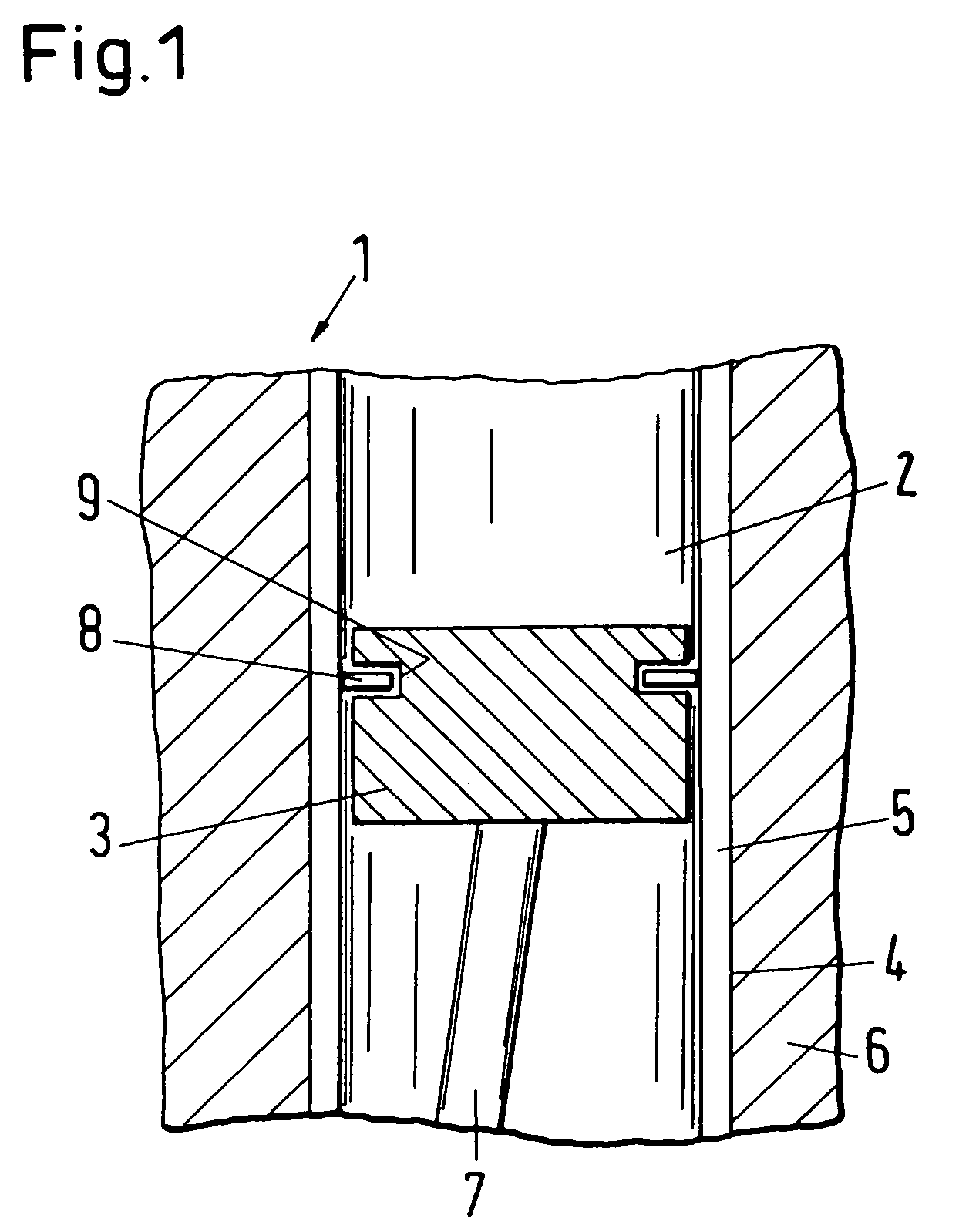
[0047]FIG. 1 shows in a schematic illustration a reciprocating piston compressor with a surface layer formed from the material of the invention. An example of a compressor in accordance with the invention, which is particularly important in practice and which is designated in the following as a whole with the reference numeral 1, is schematically shown in section in FIG. 1.

[0048]The reciprocating piston compressor 1 includes, in a manner known per se, essentially a cylinder 6 in which a compression chamber 2 is formed in which a piston 3 is arranged for to and fro movement for the compression of a gas in a similar manner to a reciprocating piston combustion engine. The compression chamber 2 is bounded by the cylinder wall 4, by the piston 3 which is movably arranged therein and by a cylinder head which is not shown here. The movement of the piston 3 in the cylinder 6 is generated via a connecting rod 7 which is connected to a likewise non-illustrated crankshaft, with the crankshaft ...


PUM

PropertyMeasurementUnit
Fractionaaaaaaaaaa
Percent by massaaaaaaaaaa

Abstract

The invention relates to a material based on an oxide ceramic for the manufacture of a surface layer (5) by means of a thermal coating process including aluminum oxide and zirconium oxide, with the material additionally containing chromium oxide for the simultaneous optimization of the hardness and toughness of the surface layer (5).

Description

BACKGROUND OF THE INVENTION[0001]The invention relates to a material and to a process for thermal coating, to a surface layer of the material and also to a compressor with such a surface layer.[0002]Ceramic coatings applied by thermal spraying have been known for a long time for a multitude of applications. Thus, by way of example, surfaces of oil lubricated cylinder running surfaces in vehicle engines have already been coated for some time by plasma spraying amongst other things, with the layer significantly reducing above all the coefficient of friction which is effective between the piston rings and the cylinder wall whereby the wear of the piston rings and the cylinder is significantly reduced, which leads to an increase of the working life of the engine, to a prolongation of the service intervals, for example between oil changes, and not least to a notable increase in the performance of the engine. This is achieved by different measures. For example such layers can contain depo...

Claims


Application Information

Patent Timeline
IPC IPC(8): C23C4/10B32B9/00
CPCC04B35/119C04B35/62665C23C4/105F04B39/126C04B2235/3218C04B2235/322C04B2235/3225C04B2235/3232C04B2235/3241C04B2235/5436C04B2235/76C04B2235/765C04B2235/80C04B2235/96F05C2203/0869F05C2203/0895F05C2253/12Y02T50/67C23C4/11Y02T50/60
Inventor BARBEZAT, GERARD
Owner SULZER METRO AG
Why Eureka
Try Eureka