
Fuel injection system

a fuel injection system and fuel injection technology, applied in the direction of positive displacement liquid engines, piston pumps, machines/engines, etc., can solve the problems of inability to ensure sufficient durability of in-cylinder direct injection engines, inability to meet the requirements of combustion, wear and seizure of sliding parts in injectors and nozzles, etc., to achieve the effect of reducing fuel costs

Inactive Publication Date: 2007-10-23
DENSO CORP
View PDF5 Cites 18 Cited by
  • Summary
  • Abstract
  • Description
  • Claims
  • Application Information

AI Technical Summary

Benefits of technology

The invention is a fuel injection system for internal combustion engines that can inject both liquid and gaseous fuel. The system includes a gaseous fuel supplying unit, a liquid fuel supplying unit, an injector, a pressure feeding unit, a pressure increasing unit, and a recovery flow passage. The system can control the injection ratio of gaseous fuel to liquid fuel by adjusting the pressure of the liquid fuel. The recovered gaseous fuel can be used as fuel for the engine, reducing fuel costs. The technical effects of the invention include improved fuel efficiency, control over injection ratio, and cost reduction.

Problems solved by technology

There is a limit in meeting these requirements with the combustion of fossil liquid fuel in conventional engines.
With conventional gaseous fuels, sufficient durability cannot be ensured in in-cylinder direct injection engines because of their poor lubricity.
Specifically, various problems, including wear and seizure in sliding parts in injectors and nozzles and poor sealability for fuel due to wear in valve seats, have arisen.
In compression ignition engines, such fuels as hydrogen and compressed natural gas low in cetane number are inferior in ignitability, and they make operation unstable.
However, this method has a drawback.
However, this method also has drawbacks.
The construction is complicated, and mineral seal oil pressure is constantly applied to a needle seal groove, which causes the mineral seal oil to constantly leak into working fluid and gaseous fuel.
However, this method also involves a problem.
It is difficult for working fluid to get into the lower part of the mineral seal oil sump, e.g., the nozzle hole side of the sump, because of gaseous fuel pressure; therefore, the lubricity for the lower part of a needle cannot be ensured.
However, these methods have drawbacks that wear in a valve seat cannot be reduced and fine liquid fuel injection for ensuring ignitability cannot be carried out.
Gaseous fuel is prone to leak; namely, a leak may occur from an injector having a portion, where metallic surfaces are in tight contact, and get out of a fuel circuit.
These methods are not provided with a construction or a function for coping with leaking gaseous fuel.

Method used


Image

  • Fuel injection system
  • Fuel injection system
  • Fuel injection system

Examples


first embodiment

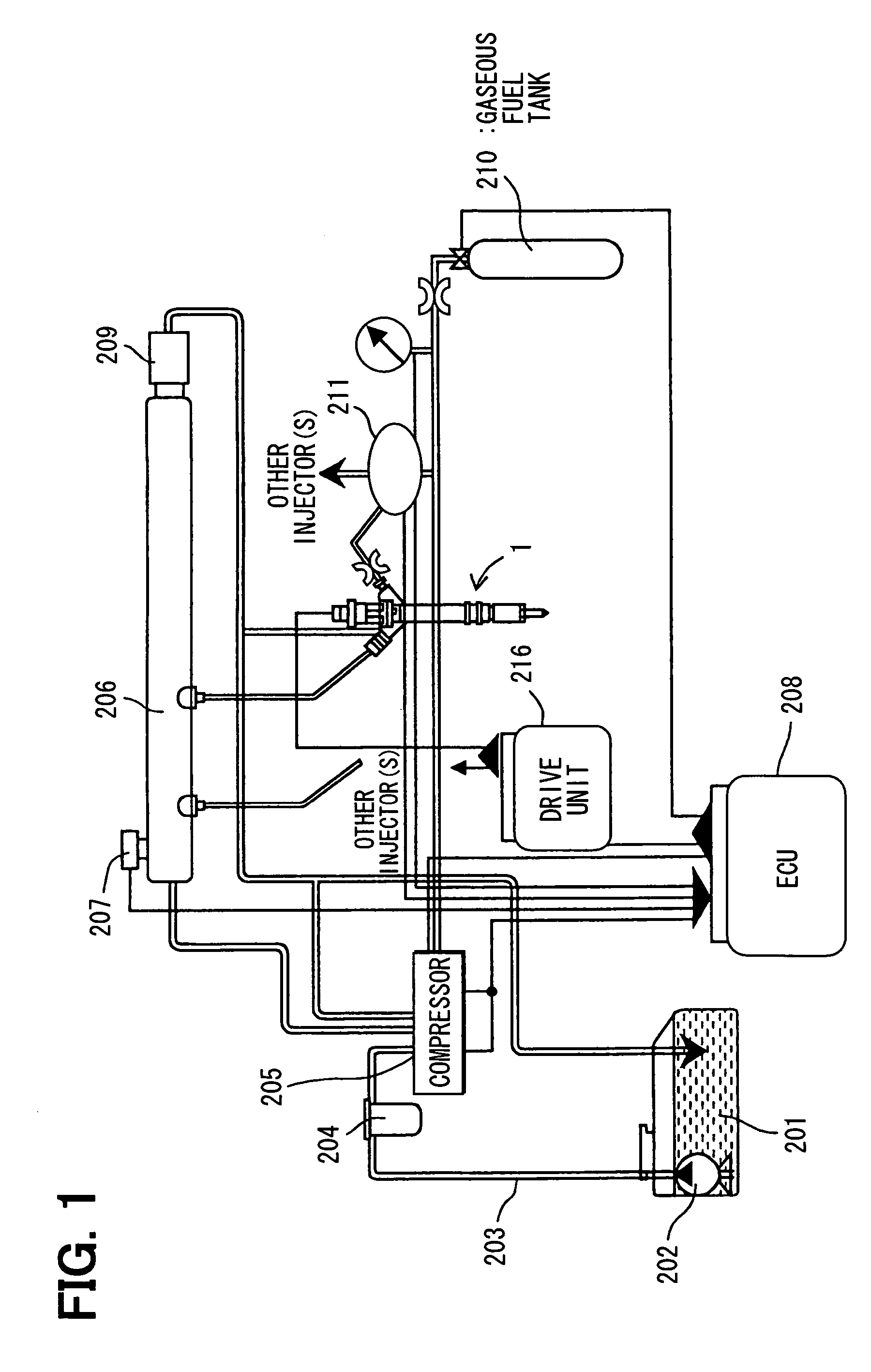
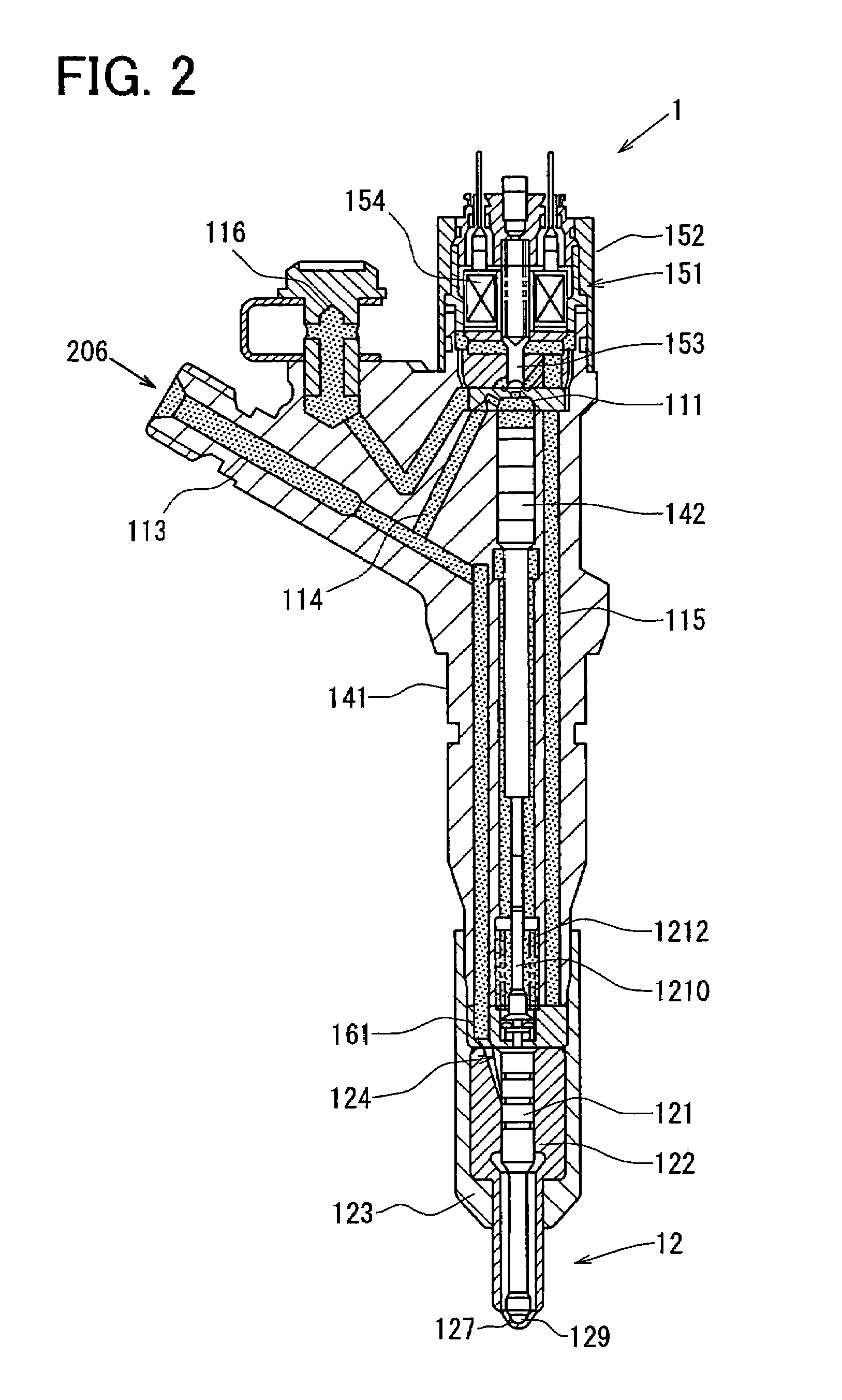
[0038]A fuel injection system is fabricated as an embodiment of the invention. FIG. 1 illustrates a configuration of the fuel injection system in this embodiment.

[0039]The fuel injection system in this embodiment pressure feeds liquid fuel such as light oil and gaseous fuel such as hydrogen to an injector 1 as one of multiple injectors, and injects them from the injector 1. Description will be given to the configuration of the fuel injection system in this embodiment, together with paths for fuels.

[0040]First, description will be given to the path through which liquid fuel such as light oil is pressure fed to the injector 1.

[0041]The light oil (liquid fuel) to be injected from the injector 1 is stored in a liquid fuel tank 201. The light oil is drawn from the liquid fuel tank 201 by a feed pump 202. The liquid fuel goes through a pipe 203. Fine dust, moisture, and foreign matter mixed in the liquid fuel are removed through a filter 204. Then, the light oil is pressurized to a predet...

second embodiment

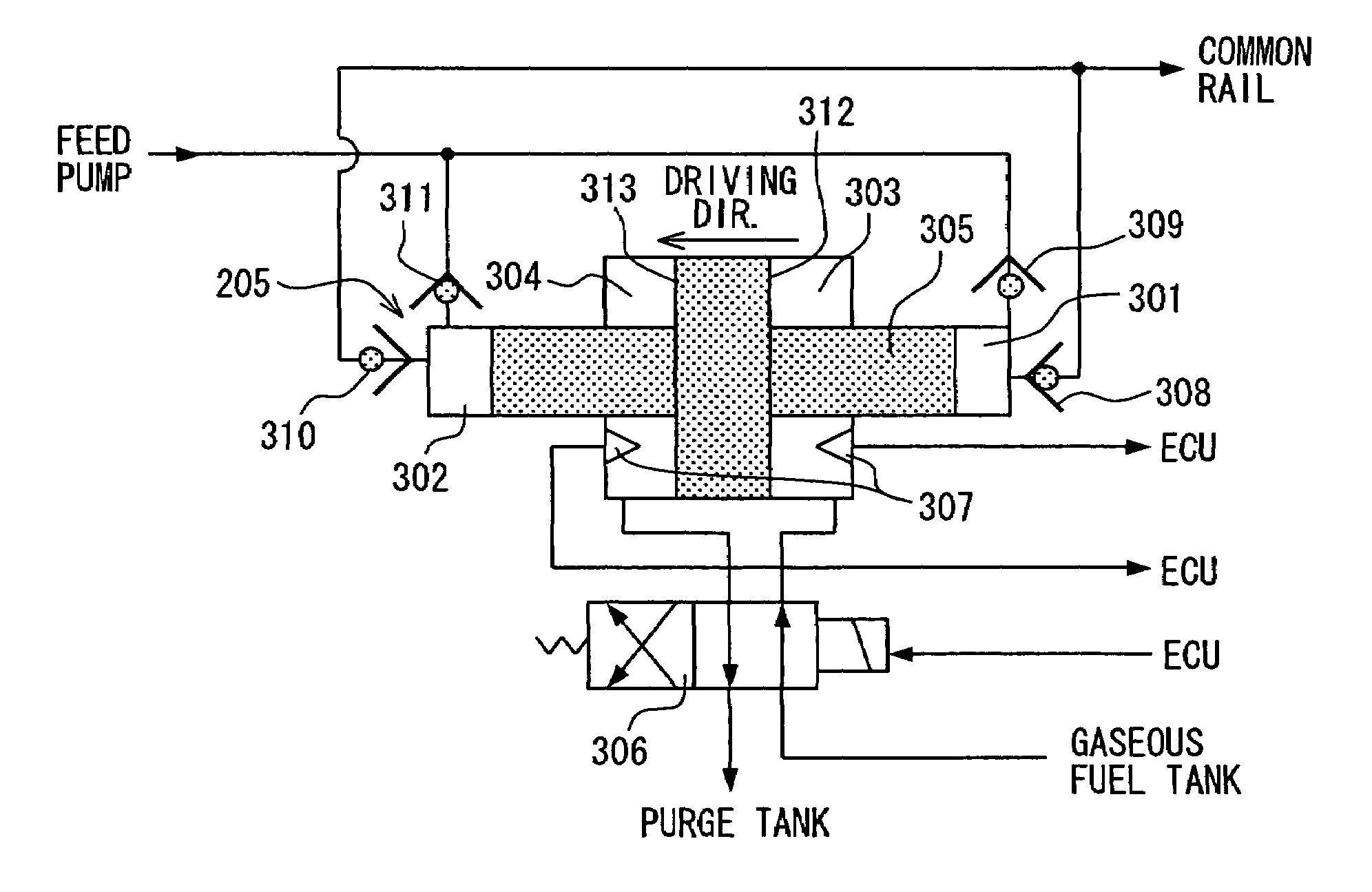
[0081]This embodiment is a modification to the first embodiment. It is a system having a compressor 205, structure of which is simplified by disusing the pipe extending from the feed pump 202 to the first control chamber and the pipe extending from the first control chamber to the common rail. FIG. 10 shows the compressor 205 in this embodiment. The members of the compressor 205 in this embodiment, that are not specially referred to are those having the same function and structure as of the compressor in the first embodiment.

[0082]The liquid fuel pressure fed from the feed pump 202 pushes a third valve 410 open and goes into a second control chamber 402. At this time, the gaseous fuel pressure fed from the gaseous fuel tank 210 goes into a third control chamber 403 by way of a pressure control valve 406.

[0083]When the gaseous fuel pushes the plane A 412 of a pressure piston 405, the pressure piston 405 slides to the left. When the pressure piston 405 slides to the left, the volumetr...

third embodiment

[0085]This embodiment is a modification to the first embodiment and is a system having a compressor 205 illustrated in FIG. 11. The members of the compressor 205 in this embodiment, that are not specially referred to are those having the same function and structure as of the compressor in the first embodiment.

[0086]The compressor 205 is constructed of a first control chamber 501, second control chamber 502, third control chamber 503, fourth control chamber 504, pressure piston 505, pressure control valve 506, position sensor 507, first valve 508, second valve 509, third valve 510, and fourth valve 511.

[0087]The compressor 205 in this embodiment is different from the compressor in the first embodiment in that the destinations of pipes for gaseous fuel and liquid fuel are reverse. That is, the first valve 508 and the second valve 509 are connected to the third control chamber 503, and the third valve 510 and the fourth valve 511 are connected to the fourth control chamber 504.

[0088]Th...


PUM


Abstract

A fuel injection system includes (i) an injector for injecting gaseous fuel and liquid fuel into a cylinder of an internal combustion engine, (ii) a gaseous fuel supplying unit having a gaseous feel tank as a first high-pressure accumulating source for pressurizing gaseous fuel, (iii) a liquid fuel supplying unit having a common rail as a second high-pressure accumulating source for pressurizing liquid fuel; (iv) a fuel pump as a pressure feeding unit that pressure feeds liquid fuel to the common rail; and (v) a compressor as a pressure increasing unit, which is operated under pressure of the pressurized gaseous fuel to increase pressure of liquid fuel pressure fed from the fuel pump.

Description

CROSS REFERENCE TO RELATED APPLICATION[0001]This application is based on and incorporates herein by reference Japanese Patent Application No. 2005-352416 filed on Dec. 6, 2005.FIELD OF THE INVENTION[0002]The present invention relates to a fuel injection system that injects liquid fuel and gaseous fuel into a cylinder of an internal combustion engine.BACKGROUND OF THE INVENTION[0003]Recently, importance has been placed on the cleanliness of exhaust gas and reduction in the discharge of CO2 with respect to automobile engines and the like. There is a limit in meeting these requirements with the combustion of fossil liquid fuel in conventional engines. There have been commercialized or developed gas combustion engines that burn such fossil fuel as gaseous fuel derived from natural gas, petroleum gas, and moreover hydrogen gas.[0004]With conventional gaseous fuels, sufficient durability cannot be ensured in in-cylinder direct injection engines because of their poor lubricity. Specificall...

Claims


Application Information

Patent Timeline
Patent Type & Authority Patents(United States)
IPC IPC(8): F02B43/00F02M59/00F04B17/00
CPCF02M21/0254F02D19/0684F02M61/042F02M61/1893F02M63/0225F02M63/029F02D19/0621F02D19/0644F02D19/0694F02M21/0263F02D19/0605F02B2275/14F02M47/027F02M63/0015F02M63/004F02M63/0047Y02T10/36Y02T10/123Y02T10/32Y02T10/12Y02T10/30
Inventor KATO, MASAAKIAKIMOTO, KATSUHIDE
Owner DENSO CORP
Learn More