
Toner for developing latent electrostatic image, container having the same, developer using the same, process for developing using the same, image-forming process using the same, image-forming apparatus using the same, and image-forming process cartridge using the same

a technology for developing electrostatic images and toners, which is applied in the direction of electrographic processes, electrographic processes, and electrographic processes using charge patterns, etc. it can solve the problems of excessive amount of toners melted and stuck to the heating roller, poor image fixing, and hot offset, etc., to achieve excellent powder fluidity, excellent heat storage properties, and excellent powder fluidity

Inactive Publication Date: 2007-01-02
RICOH KK
View PDF21 Cites 34 Cited by
  • Summary
  • Abstract
  • Description
  • Claims
  • Application Information

AI Technical Summary

Benefits of technology

[0035]It is therefore an object of the present invention to provide a toner for developing an electrostatic image having excellent powder fluidity, development properties and transfer properties together with excellent heat storage properties, low temperature image-fixing properties and hot offset properties when used as a toner having a small particle diameter, having good and stable development properties over long periods of use and which can form high-quality images, and in particular to provide a toner for developing an electrostatic image having excellent image glossiness when used in full color copiers, and having a long lifetime.
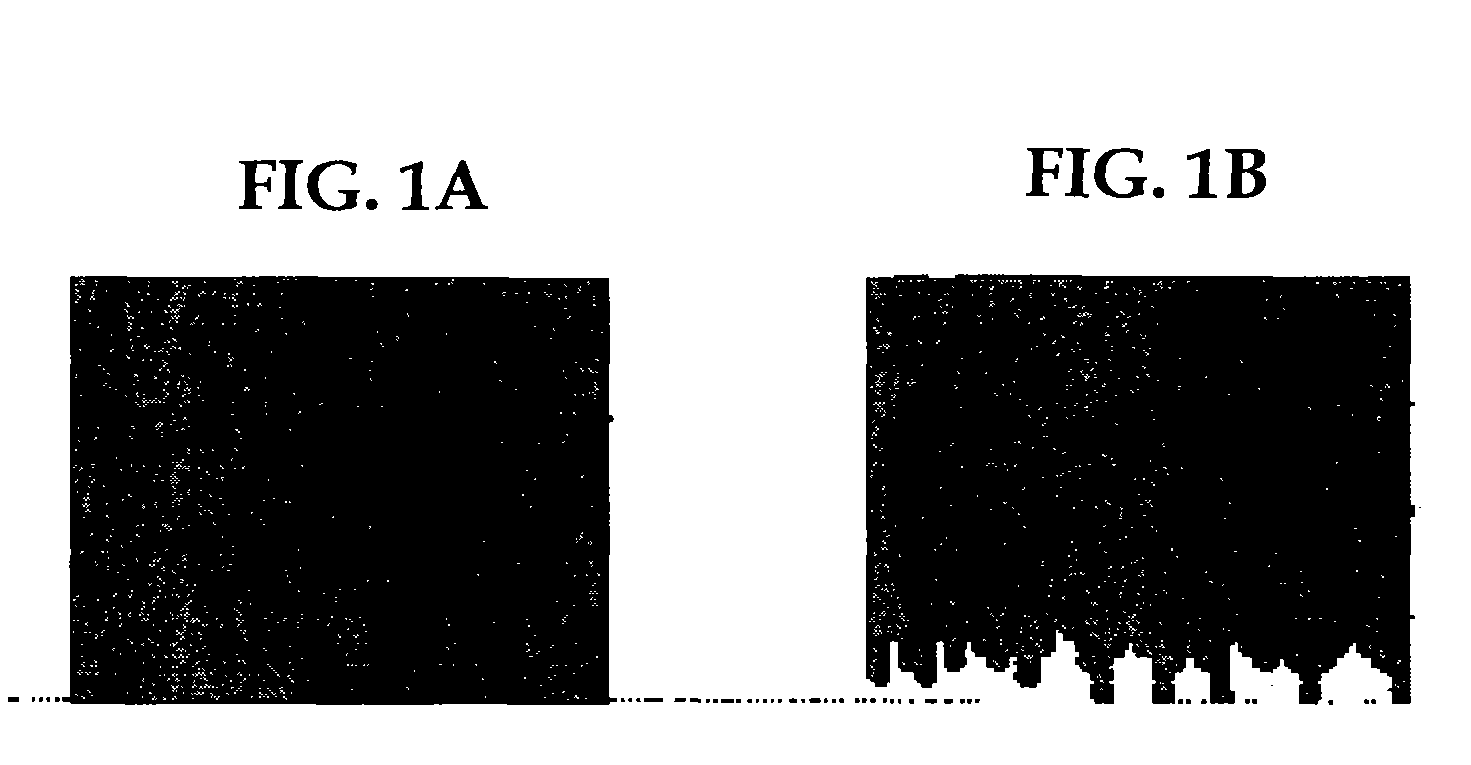
[0037]It is yet another object of the present invention to provide an image-forming process using the developer of the present invention, in which, while increasing the magnetic brush density so as to give sufficient image density, abnormal images such as “image omission at rear end” at low contrast can be prevented, and images having good reproducibility of horizontal line and dot without edge effects can be obtained in a long period of time, taking the deterioration of the toner with time into consideration, and to provide an image-forming apparatus which comprises the developer of the present invention.

Problems solved by technology

If the temperature of the heating roller is too high, hot offset may occur in which excessive amount of toners become melted and stuck to the heating roller.
Conversely, if the temperature of the heating roller is too low, the toners do not melt properly and thus image-fixing is poor.
However, the process of applying the silicone oil to the heating roller requires an oil tank and oil coating equipment, which makes the apparatus complex and bigger.
It has also led to deterioration of the heating roller and the need for maintenance has to be carried out periodically.
Furthermore, adhesion of oil to copy papers or OHP (overhead projectors) film cannot be avoided.
In OHP, particularly, there is a problem of poor color tone due to oil adhesion.
This produces submicron particles or results in having fluidizers embedded on the toner surface.
An image quality therefore deteriorates.
Also, due to the formation and poor fluidity (fluidability) of the toner as powder, the toner is required to be more fluidized, less of the toner is filled in the toner bottle, and it is therefore difficult to make the apparatus smaller.
In order to produce full color images, the transfer of multi-color toner from the photoconductor onto a transferring medium or paper is also complicated.
Due to poor transfer properties resulting from the non-defined particle formation of the pulverized toner, there are problems that image dropout occurs, that more toner is required to cover the dropout, and the like.
However, the toners disclosed in (1) to (3) all have poor powder fluidity and transfer properties, and decreasing the particle diameter does not allow high quality images.
Further, regarding the toners of (1) and (2), heat storage properties and low temperature image-fixing properties cannot be obtained at the same time, and glossiness cannot be obtained with full color, so they were not practical.
Regarding the toner of (3), low temperature image-fixing properties are inadequate and hot offset properties in oil-less image-fixing are unsatisfactory.
The toners of (4) and (5) do have improved powder fluidity and transfer properties, however, for the toner of (4), low temperature image-fixing properties are poor and a large amount of energy was required for image-fixing.
These problems are particularly evident for full color toners.
For the toner of (5), low temperature image-fixing properties are much better, however, hot offset resistance is poor and when used for full color, oil coating of the heating roller cannot be dispensed with.
As the fluidizer becomes embedded in the toner surface, image quality tends to deteriorate, and the life of toner is thereby shortened.
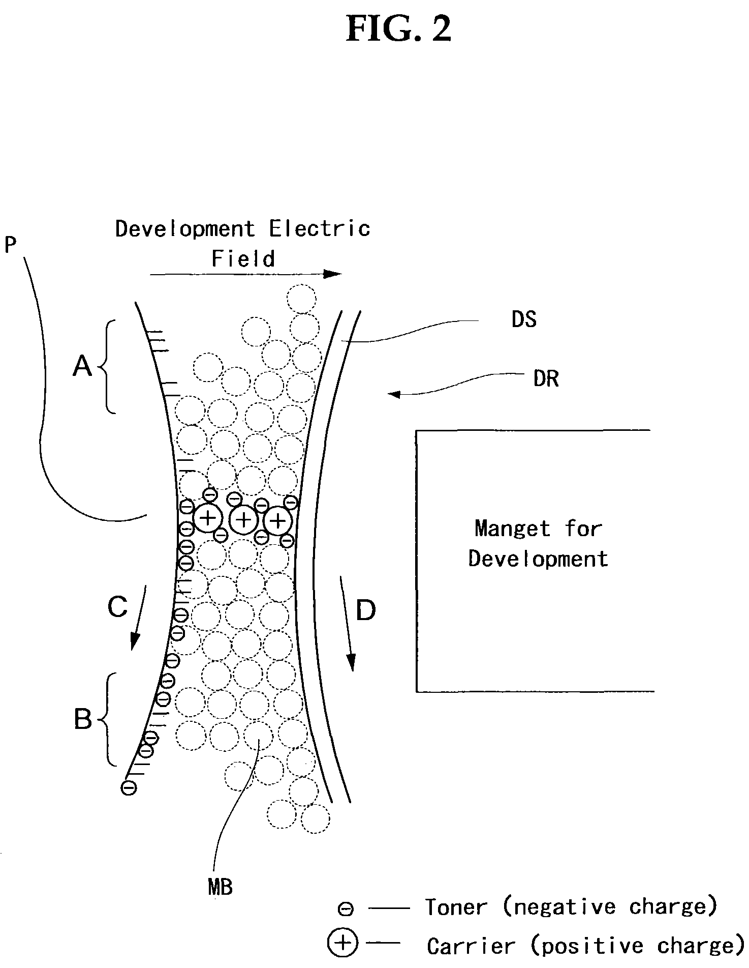
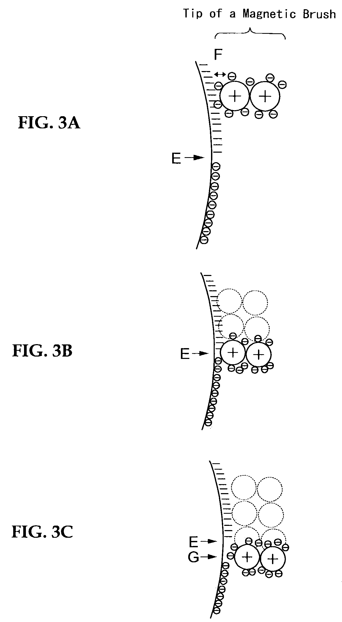
Conventionally, in this double-component developing process, developing conditions which allows sufficient image, density are not compatible with those which allow low contrast images.
It has been hence difficult to simultaneously improve high density parts and low density parts.
In other words, these two sets of developing conditions are contradictory from each other, and are not compatible.
Therefore, it is generally considered difficult to obtain a high quality image satisfying both sets of developing conditions over the whole range of the density.
Due to a similar mechanism, horizontal lines are thinner than vertical lines (horizontal line thinning) and the formation of isolated dots is unstable, which makes it difficult to obtain high image quality by the development using magnetic brushes formed of a double-component developer.
However, it is known that the image omission at rear end cannot be completely suppressed merely by decreasing the half-value width of the magnetic pole for development.
However, if the above image-forming process (1), (2), (3), and (4) which increase the magnetic brush density to prevent abnormal images that have “image omission at rear end” is employed, the developer in the development nip part has a higher contacting force (impact force) given on the photoconductor, compared to the case when the magnetic brush density is low, and a high stress is easily given on the developer (and toners contained in the developer), so the toners tend to deteriorate with time, charge is lost and toner scattering or toner deposition on background of the image tend to occur.
Due to this, image deterioration with time as compared to the initial image, becomes much more apparent.
In particular, when a toner having a relatively wide toner charge distribution is used, this is a very serious problem.

Method used


Image

  • Toner for developing latent electrostatic image, container having the same, developer using the same, process for developing using the same, image-forming process using the same, image-forming apparatus using the same, and image-forming process cartridge using the same
  • Toner for developing latent electrostatic image, container having the same, developer using the same, process for developing using the same, image-forming process using the same, image-forming apparatus using the same, and image-forming process cartridge using the same
  • Toner for developing latent electrostatic image, container having the same, developer using the same, process for developing using the same, image-forming process using the same, image-forming apparatus using the same, and image-forming process cartridge using the same

Examples


example a-1

(Synthesis of Binder Resin)

[0194]724 parts of bisphenol A ethylene oxide dimolar adduct, 276 parts of isophthalic acid and 2 parts of dibutyl tin oxide were introduced into a reaction vessel equipped with a condenser, stirrer and nitrogen inlet tube, were reacted under normal pressure at 230° C. for 8 hours, were reacted again under a reduced pressure of 10–15 mmHg for 5 hours and cooled to 160° C., then 32 parts of phthalic anhydride was added and the reaction was continued for 2 hours. Next, the reaction mixture was cooled to 80° C., and 188 parts of isohorone diisocyanate was added in ethyl acetate and reacted for 2 hours to obtain a prepolymer (1) containing isocyanate. Next, 267 parts of the prepolymer (1) and 14 parts of isohorone diamine were reacted at 50° C. for 2 hours to obtain a urea-modified polyester resin (1) having a weight average molecular weight of 64000. In an identical manner to that of the above, 724 parts of bisphenol A ethylene oxide dimolar adduct and 276 pa...

example a-2

(Synthesis of Binder Resin)

[0196]In an identical manner to that of Example A-1, 334 parts of bisphenol A ethylene oxide bimolar adduct, 274 parts of isophthalic acid and 20 parts of anhydrous trimellitic acid were condensation polymerized, and reacted with 154 parts of isohorone diisocyanate to obtain a prepolymer (2). Next, 213 parts of the prepolymer (2), 9.5 parts of isohorone diamine and 0.5 parts of dibutylamine were reacted in the same way as that of Example A-1 to obtain a urea-modified polyester resin (2) having a weight average molecular weight of 79000. 200 parts of the urea-modified polyester resin (2) and 800 parts of the non-modified polyester resin (a) were dissolved in 2000 parts of ethyl acetate / MEK (1 / 1) mixed solvent, and stirred to obtain an ethyl acetate of the binder resin (2). This was dried under partial reduced pressure to isolate the binder resin (2). The peak molecular weight was 5000, Tg was 62° C. and the acid value was 10.

(Toner Preparation)

[0197]The ide...

example a-3

(Binder Resin Synthesis)

[0198]30 parts of the urea-modified polyester resin (1) and 970 parts of the non-modified polyester resin (a) were dissolved in 2000 parts of ethyl acetate / MEK (1 / 1) mixed solvent, and stirred to obtain an ethyl acetate / MEK solution of the binder resin (3). This was dried under partial reduced pressure to isolate the binder resin (3). The peak molecular weight was 5000, Tg was 62° C. and the acid value was 10.

(Preparation of Toner)

[0199]The toner (3) of the present invention was obtained in an identical manner to that of Example A-2, except that the binder resin (2) was replaced by the binder resin (3), and the coloring agent was changed to 8 parts of carbon black. The volume average particle diameter (Dv) of the base of toner particle was 6.82 μm, the number average particle diameter (Dn) of the base of toner particle was 6.11 μm, and the ratio (Dv / Dn) was 1.12. Other detailed conditions and test results are shown in Tables 3 and 4.


PUM

PropertyMeasurementUnit
particle diameteraaaaaaaaaa
Tgaaaaaaaaaa

Abstract

A toner for developing a latent electrostatic image including a base of toner particle which contains a binder resin and a coloring agent, and an external additive. Herein, a plurality of the base of toner particle has a volume average particle diameter (Dv) of 3 μm to 7 μm, a ratio (Dv / Dn) of the volume average particle diameter (Dv) to a number average particle diameter (Dn) is 1.01 to 1.25, a plurality of the base of toner particle contains 15% by number or less of the base of toner particle having a particle diameter of 0.6 μm to 2.0 μm, a plurality of the base of toner particle has a circularity of 0.930 to 0.990 on average, the binder resin contains a modified polyester resin, and the toner contains 0.3 parts by weight to 5.0 parts by weight of the external additive, relative to 100 parts by weight of the base of toner particle.

Description

BACKGROUND OF THE INVENTION[0001]1. Field of the Invention[0002]The present invention relates to a toner for developing electrostatic images in electrophotography, electrostatic recording or electrostatic printing, to a developer which comprises the toner, and to an image-forming process and image-forming apparatus using the developer which comprises the toner. More specifically, the present invention relates to a toner for developing an electrostatic image used in copiers, laser printers and fax machines that utilize plain paper using direct or indirect electrophotographic developing process, to a developer which comprises the toner, and to an image-forming process and an image-forming apparatus using the developer which comprises the toner. It further relates to a toner for developing an electrostatic image used in full color copiers, full color laser printers and full color fax machines that utilize plain paper using the direct or indirect electrophotographic multicolor image-for...

Claims


Application Information

Patent Timeline
Patent Type & Authority Patents(United States)
IPC IPC(8): G03G9/08G03G13/09G03G9/087G03G9/097
CPCG03G9/0819G03G9/0821G03G9/0827G03G9/09725G03G9/08795G03G9/08797G03G9/08755
Inventor TOMITA, MASAMITAKIKAWA, TADAOICHIKAWA, TOMOYUKISASAKI, FUMIHIRONANYA, TOSHIKIHIGUCHI, HIROTOEMOTO, SHIGERUYAGI, SHINICHIROSHIMOTA, NAOHITOKONDO, MAIKO
Owner RICOH KK
Learn More