
Metalothermic reduction of refractory metal oxides

a technology of refractory metal oxides and metalothermic reduction, which is applied in the direction of titanium suboxides, chromium oxides/hydrates, fixed capacitor details, etc., can solve the problems of insufficient time for significant energy and mass exchange with the surrounding, and achieve the elimination of halide by-products and carbon contamination, and high quality

Inactive Publication Date: 2006-12-19
TANIOBIS GMBH
View PDF18 Cites 11 Cited by
  • Summary
  • Abstract
  • Description
  • Claims
  • Application Information

AI Technical Summary

Benefits of technology

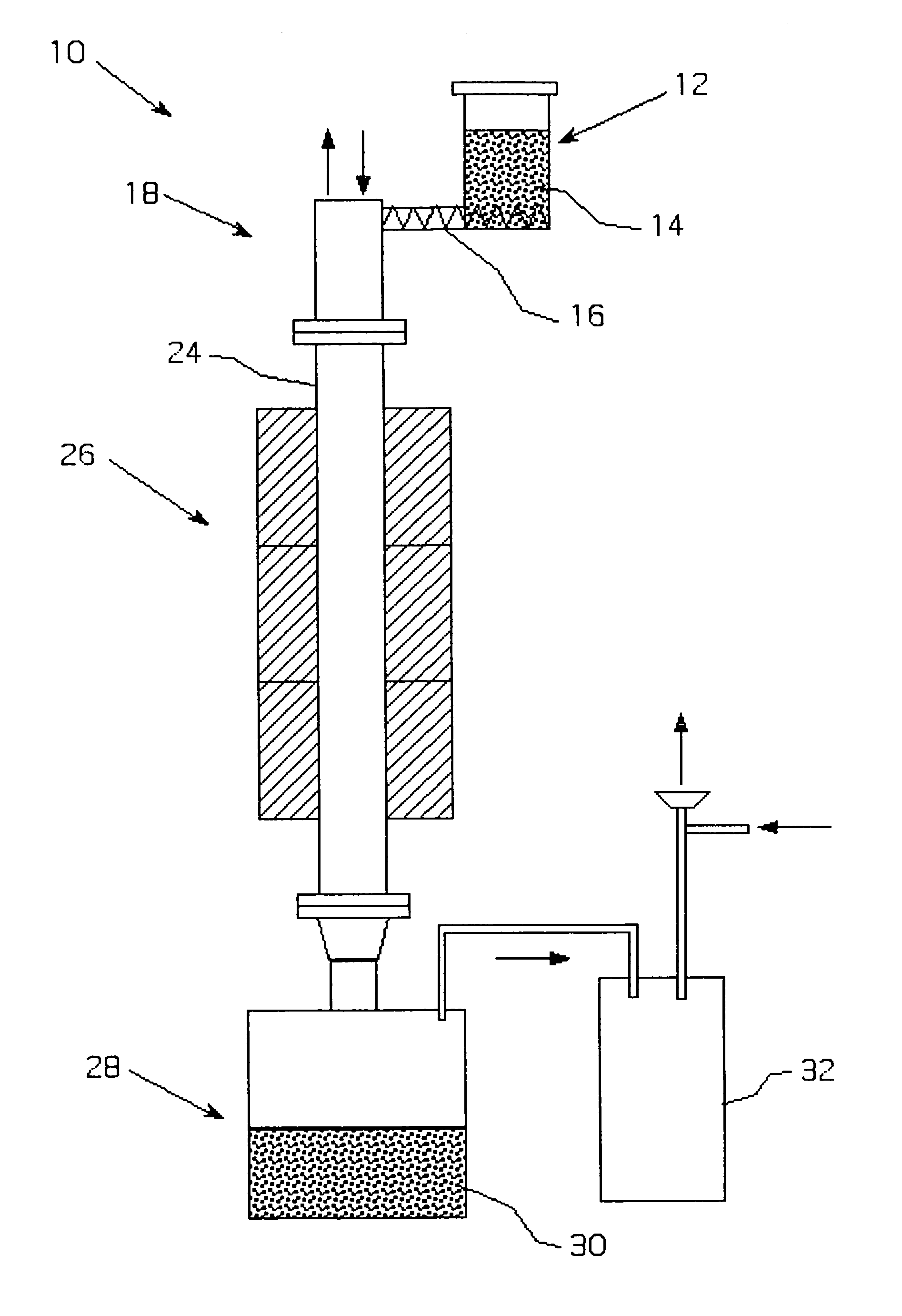
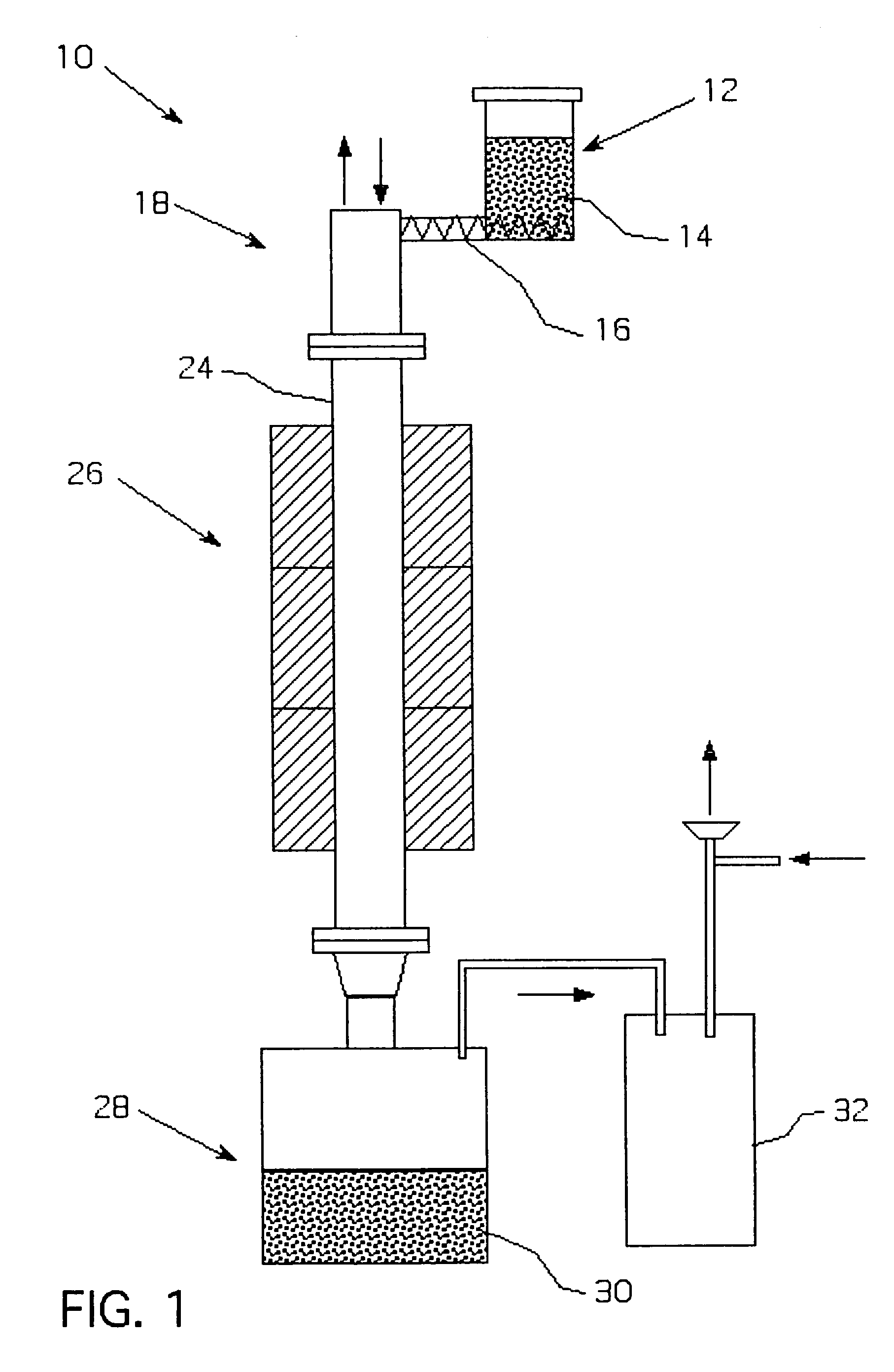
[0018]The present invention solves the problems of refractory metal oxide reduction by feeding a blend of the oxide and reducing agent directly into a reactor to achieve a self-sustaining, highly exothermic reaction (continuous magnesium reduction). The use of an oxide / reducing agent blend eliminates the problems associated with the generation and transport of gaseous metal to the reaction zone. The completion of the reduction and the physical properties of the metal powder can be controlled during the process.
[0022]The present invention also shows that the self-sustaining reaction zone position and its temperature can be efficiently controlled by maintaining a consistent feeding rate, ignition (furance) temperature, and inert carrier gas flow rate. Achieving a consistent oxide flow is not a trivial issue since some of the refractory metal oxides are dielectrics and have a natural tendency to accumulate static electricity due to the friction of the oxide particles against each other. Agglomerate-void formation makes it virtually impossible to maintain a consistent feeding over time and adversely impacts both the kinetics and the control of the reduction reaction.
[0023]We discovered that feeding a blend of oxide and metal powder (Mg, Ca, Al, etc.) helps to dissipate the static electricity and break up the agglomerates. The metal powder should be fine enough to vaporize / melt rapidly in the reaction zone. As a result of the use of blends, material flowability is significantly improved. This permits a stable, consistent self-sustaining reduction reaction to occur.

Problems solved by technology

While the reactor system of this invention is not adiabatic, it can approach this condition because of the extremely rapid reaction rate and, therefore, there is insufficient time for significant energy and mass exchange with the surroundings.

Method used


Image

  • Metalothermic reduction of refractory metal oxides
  • Metalothermic reduction of refractory metal oxides
  • Metalothermic reduction of refractory metal oxides

Examples


example 1

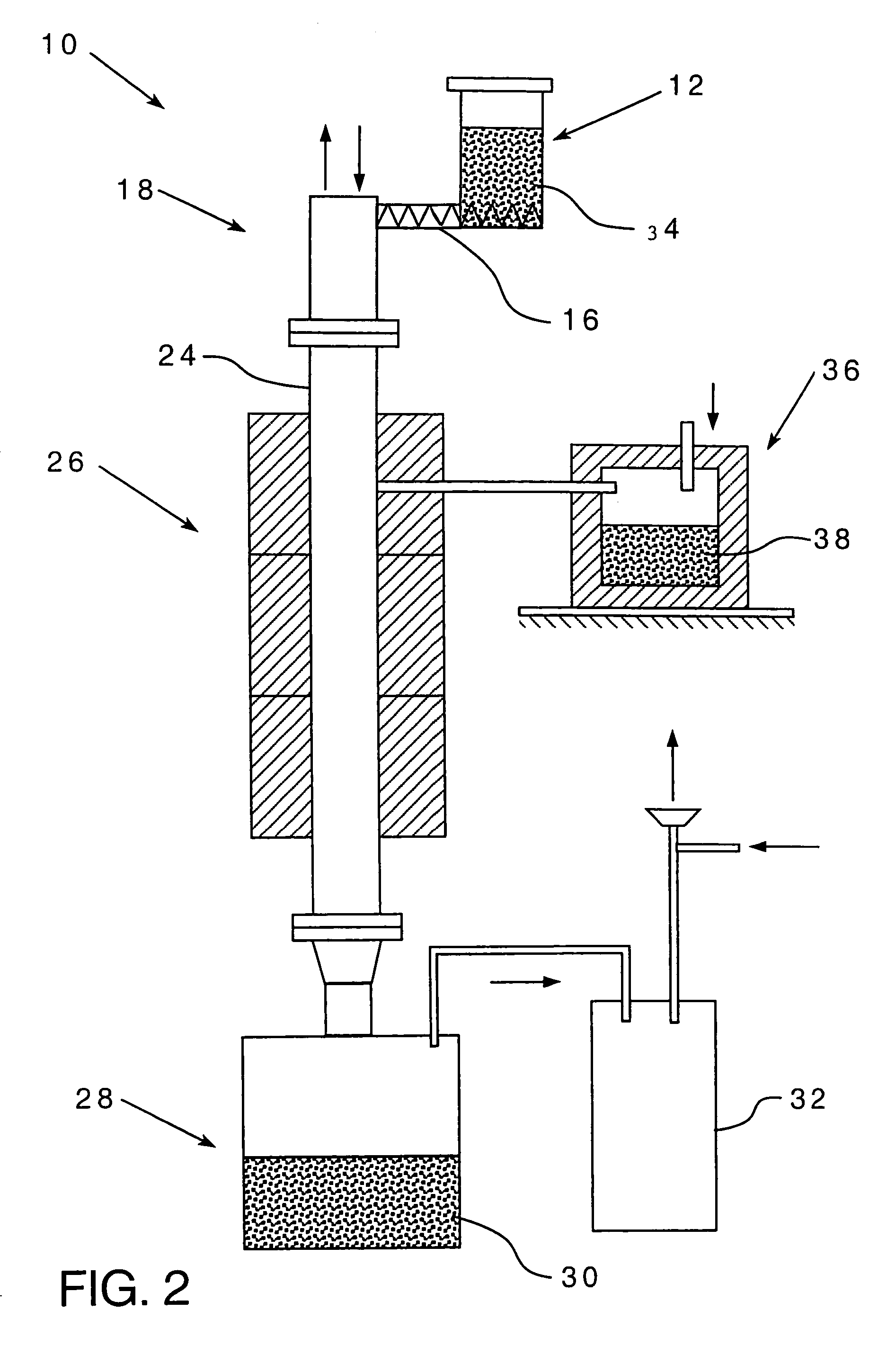
[0046]Tantalum pentoxide was reduced with gaseous magnesium as shown in FIG. 2. The temperature in the magnesium melter was 975° C., while the temperature in the furnace was maintained at 985° C. to prevent magnesium condensation on the cold parts. The argon flow through the melter and the furnace was 55 scfh. The average oxide feeding rate 1.5 kg / h. The reduction lasted 3 hours. After passivation, the receiver was opened and the products were leached with dilute sulfuric acid to remove residual magnesium and magnesium oxide. The cake was then dried in the oven at 65° C. and analyzed. The surface area of the reduced powder was 17 m2 / g, the bulk density was 26.8 g / in3, and the oxygen content was 13.2 W / W %. The reduction was only 60% complete due to the inability to maintain a consistent oxide and magnesium feed rates, which caused instability in the self-sustaining reaction during the course of the run.

example 2

[0047]The reaction zone temperature was estimated from energy balance calculations and the results are plotted in FIG. 3 as a function of the blend feed rate. The following assumptions were made:[0048](1) The value of the energy losses was estimated to be 30% of the energy input. This is a reasonable approximation for the furnace design used.[0049](2) The kinetics of the chemical reaction is instantaneous and is not a function of either oxide or magnesium particle size.[0050](3) The argon flow rate was 1.8 Nm3 / hr.[0051](4) The furnace temperature was 1150° C.

[0052]The graph in FIG. 3 shows the reaction zone temperature may change significantly depending on the feed rate. At 7 kg / hr blend feed rate, the reaction zone temperature does not differ from the furnace temperature while at 30 kg / hr feed rate, it exceeds the melting point of tantalum pentoxide. When the reaction zone temperature is higher than the oxide melting point, there is a real possibility of coalescence, which can adve...

example 3

[0053]FIG. 4 shows the furnace power readings during the reduction of Ta2O5 with magnesium powder as a function of time for several blend feed rates. The graph shows the value of power change as a function of blend feed rate. The higher the feed rate, the greater is the power drop. In fact, at 20 kg / hr blend feed rate the electric power input dropped from 46 to 6%. In other words, the furnace was not supplying energy to the system. This is strong evidence that a stable self-sustaining reaction exists in the reactor.


PUM

PropertyMeasurementUnit
surface areaaaaaaaaaaa
equivalent series resistanceaaaaaaaaaa

Abstract

High purity refractory metals, valve metals, refractory metal oxides, valve metal oxides, or alloys thereof suitable for a variety of electrical, optical and mill product / fabricated parts usages are produced from their respective oxides by metalothermic reduction of a solid or liquid form of such oxide using a reducing agent that establishes (after ignition) a highly exothermic reaction, the reaction preferably taking place in a continuously or step-wise moving oxide such as gravity fall with metal retrievable at the bottom and an oxide of the reducing agent being removable as a gas or in other convenient form and unreacted reducing agent derivatives being removable by leaching or like process.

Description

CROSS REFERENCE TO RELATED PATENT APPLICATIONS[0001]The present patent application is a divisional of and claims the right of priority under 35 U.S.C. § 121 of U.S. patent application Ser. No. 09 / 849,717, filed May 4, 2001, now U.S. Pat. 6,849,104 B2, which claims the right of priority under 35 U.S.C. § 119(e) of the U.S. Provisional Patent Application Ser. No. 60 / 238,999, filed Oct. 10, 2000.FIELD OF THE INVENTION[0002]This invention relates to the production of tantalum, niobium, and other refractory or valve metal powders as well as metal suboxide powders, or alloys thereof by the reduction of the corresponding metal oxide with chemically active metals such as Mg, Ca, Al, and other reducing elements in a self-sustaining reaction zone created by a highly exothermic reaction, but with sufficient control to obtain powders of desired morphology and other physical and electrical characteristics.BACKGROUND OF THE INVENTION[0003]Refractory metals are members of a group of elements that ...

Claims


Application Information

Patent Timeline
Patent Type & Authority Patents(United States)
IPC IPC(8): C22C27/02B22F1/052B22F9/20C01G23/04C01G31/02C01G33/00C01G37/02C01G39/02C01G41/02H01G9/052
CPCH01G9/04H01G9/052H01G9/0525B22F1/0096B22F1/0014B22F9/20C01G23/043C01G31/02C01G33/00C01G37/02C01G39/02C01G41/02C01P2006/14C01P2006/17C01P2006/34C01P2006/40C01P2006/80B22F2998/00B22F2201/40B22F2201/11C01P2004/03C01P2004/50C01P2004/52C01P2004/61C01P2004/62C01P2006/10C01P2006/11C01P2006/12B22F1/052B22F1/148
Inventor SHEKHTER, LEONID N.TRIPP, TERRANCE B.LANIN, LEONID L.CONLON, ANASTASIA M.GOLDBERG, HOWARD V.
Owner TANIOBIS GMBH
Learn More