Eureka AIR delivers breakthrough ideas for toughest innovation challenges, trusted by R&D personnel around the world.

Continuous method and apparatus for manufacture of uniform size flake or powder

a technology of uniform size and manufacturing method, applied in the direction of fuel cell details, final product manufacturing, climate sustainability, etc., can solve the problems of high labor intensity, high labor intensity, and inability to meet anticipated commercial production demands. , to achieve the effect of minimal labor requirements and cost effectiv

Inactive Publication Date: 2006-06-13
FUELCELL ENERGY INC
View PDF14 Cites 3 Cited by
  • Summary
  • Abstract
  • Description
  • Claims
  • Application Information

AI Technical Summary

Benefits of technology

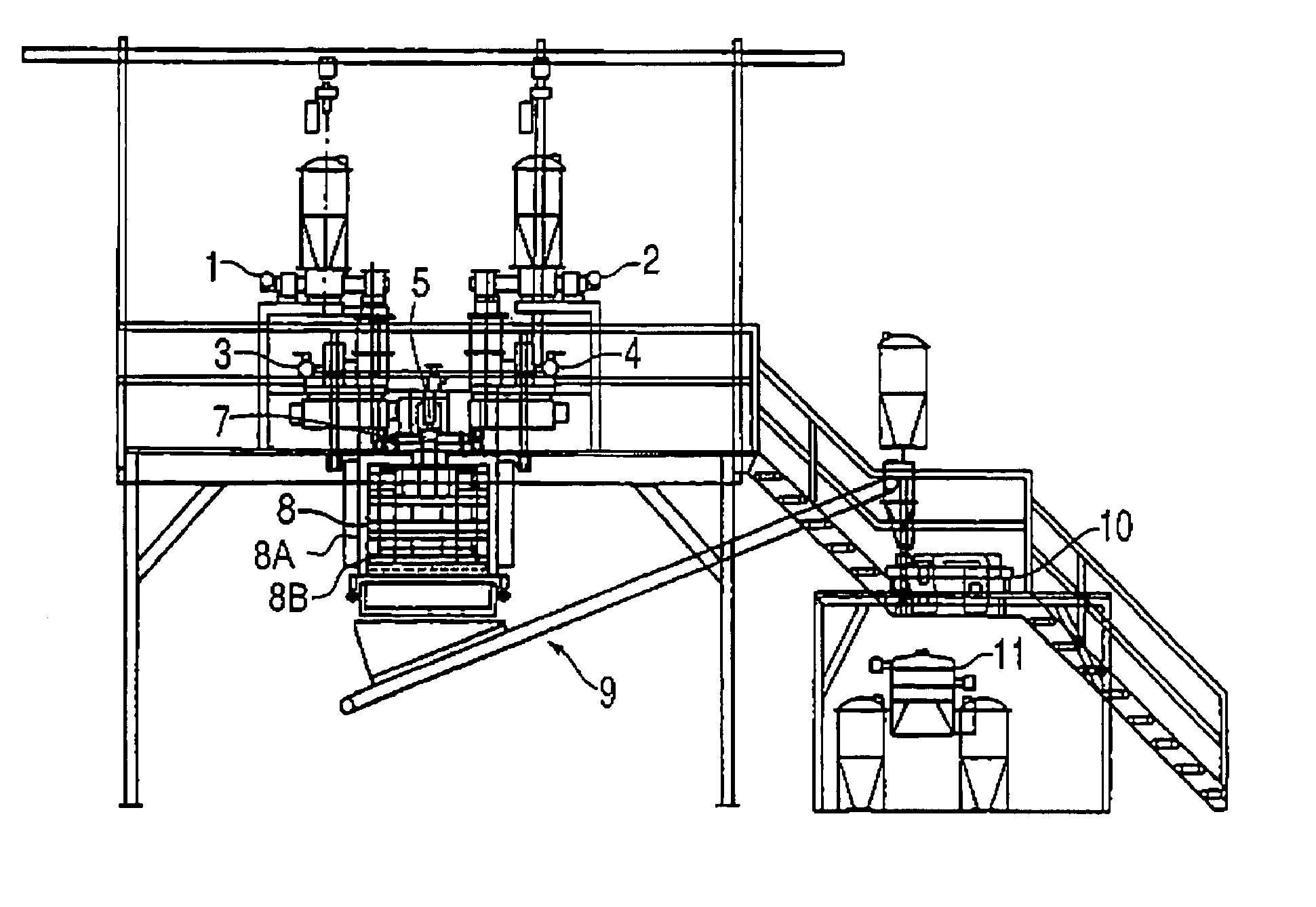
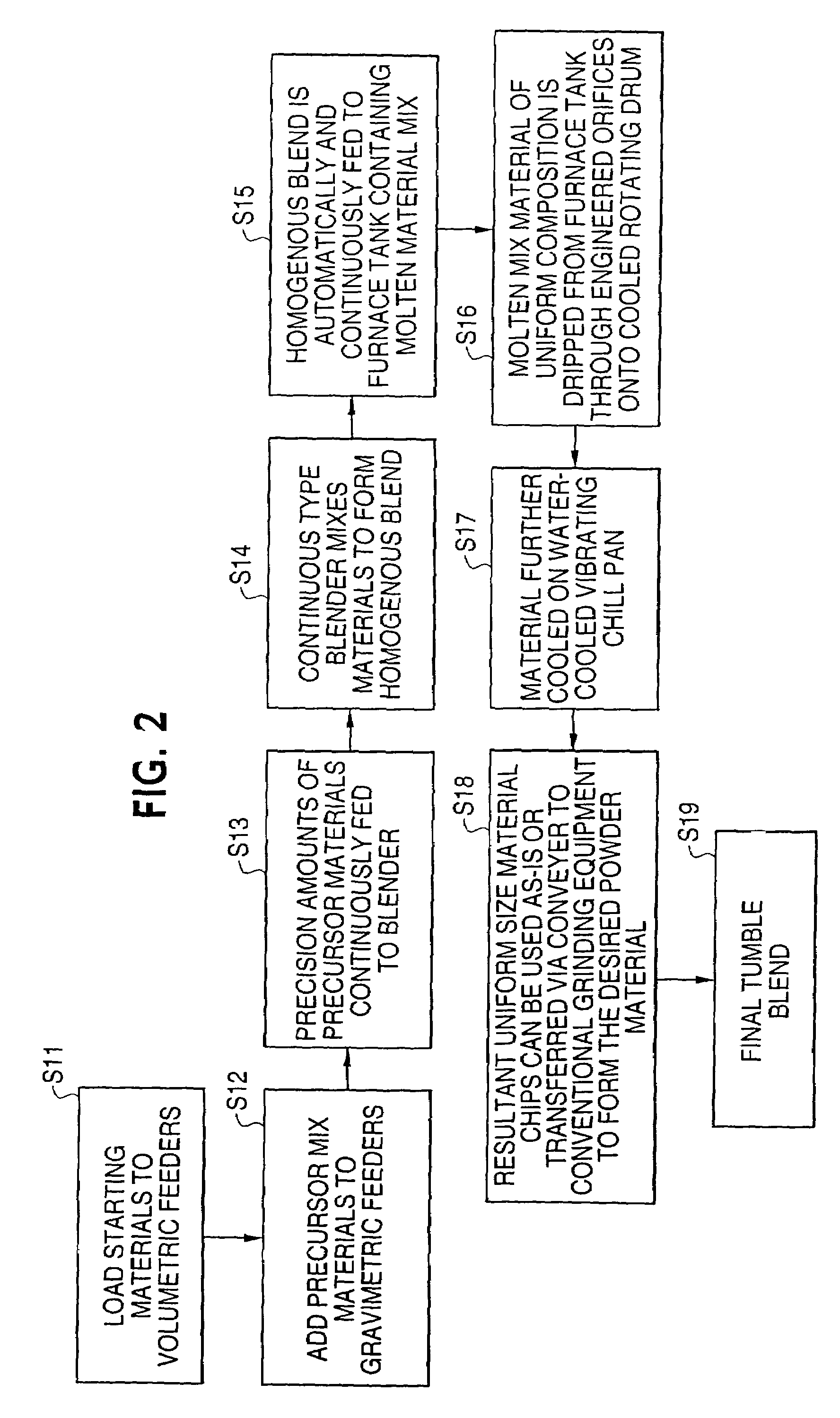
The present invention provides an innovative method for producing uniform size flake or powder materials from inorganic salts, metallic or similar materials or mixtures of such materials. The method allows for precise control of the physical characteristics of the flake or powder, such as particle size, morphology, and angle of repose. The method is cost-effective with minimal labor requirements and can continuously produce commercial quantities of electrolyte material with a precise molar composition. The method involves feeding measured amounts of precursor powders into a continuous blender, blending the powders until a homogeneous dry powder mixture is obtained, continuously adding the mixture to a high-temperature melting tank, heating the mixture so that it melts, forming a eutectic melt, cooling the melt, and removing the cooled uniform size flakes of material. The method also includes incorporating getter materials into the liquid melt zone to remove fuel-cell contaminants.

Problems solved by technology

This presents several significant challenges in light of the electrolyte requirements.
The molten mix is frozen in the crucible as a slug or is frozen into large, non-uniform chips by dumping the molten liquid into metal pans and allowing it to cool, a process known as “splat-cooling.” While the chips formed by the latter method are more desirable, splat-cooling presents considerable hazard and risk to equipment operators by exposing them to molten liquid splatter.
Such sequential batch processing method is labor intensive, expensive, and not easily scalable to meet anticipated commercial production demands.

Method used


Image

  • Continuous method and apparatus for manufacture of uniform size flake or powder
  • Continuous method and apparatus for manufacture of uniform size flake or powder
  • Continuous method and apparatus for manufacture of uniform size flake or powder

Examples


Embodiment Construction

[0024]FIG. 1 shows the process flow of a conventional method used for forming flake or dry powder fuel-cell electrolyte materials. In a first step S1, precise amounts of precursor powder materials are weighed. The precursor powders are manually added to a batch-type mixer or blender, such as a P-K type blender, ball mill or similar device in step S2, and in step S3 the powders are blended for a minimum specified time of between approximately 5 to 20 minutes to obtain a homogeneous powder mixture. In step S4, the homogeneous powder mixture is transferred to one or more high-temperature crucibles. The crucibles are transferred to a furnace in step S5, where the powder mixture is heated to above the melting point of the mixture of precursor powders. As shown in step S6, heat treatment occurs for a period of time of between approximately 30 to 120 minutes sufficient to ensure homogeneity of the molten mixture.

[0025]Once a homogeneous molten eutectic mixture is obtained, the molten liqui...


PUM

PropertyMeasurementUnit
temperatureaaaaaaaaaa
sizeaaaaaaaaaa

Abstract

A method and apparatus for continuous fabrication of homogeneous thin flake or powder electrolyte material from inorganic salt, metallic or similar materials or from mixtures of such materials for use in Carbonate Fuel Cell (“CFC”) power plants. Electrolyte precursor powders are fed to a continuous blender type mixer using precision metering equipment that controls material feed rates. The homogenous mixture of blended powders is then fed into a high temperature melting tank in which the mixture is melted, forming the desired molten eutectic composition. The liquid eutectic melt drips from the melting tank through ceramic or metallic nozzles and splat-cools on a rotating, water-cooled metal cylinder to produce uniform size, thin flake material. The thin flake electrolyte material can be used as-is, or it may be further processed using continuous grinding and powder fabrication equipment.

Description

CROSS-REFERENCE TO RELATED APPLICATIONS[0001]This application is a divisional of application Ser. No. 10 / 171,148, filed Jun. 13, 2002 now U.S. Pat. No. 6,884,269.BACKGROUND OF THE INVENTION[0002]1. Field of the Invention[0003]This invention relates to the manufacture of thin homogeneous flake or powder material from inorganic salt, metallic or similar materials or mixtures of these materials, and more particularly to a manufacturing method and equipment for the continuous production of electrolyte material used in Carbonate Fuel Cell (“CFC”) power plants.[0004]2. Description of the Related Art[0005]A fuel cell is a device that directly converts chemical energy stored in a fuel such as hydrogen or methane into electrical energy by means of an electrochemical reaction. In general, a fuel cell includes a negative or anode electrode and a positive or cathode electrode separated by an electrolyte matrix, which serves to conduct electrically charged ions between the oppositely charged ele...

Claims


Application Information

Patent Timeline
Patent Type & Authority Patents(United States)
IPC IPC(8): C21C1/00B22F9/06B01J2/02B01D9/00C01D7/00C01D7/38C01F11/18C01F11/44C22F1/00H01M8/02H01M8/14
CPCC01D7/38H01M8/0295H01M8/0693Y02E60/526H01M2008/147H01M2300/0051H01M8/145Y02E60/50Y02P70/50
Inventor LUCAS, THOMAS M.DOYON, JODY
Owner FUELCELL ENERGY INC
Why Eureka
Eureka Blog
Learn More