
Electrolytic deposition of coatings for prosthetic metals and alloys

Inactive Publication Date: 2006-03-21
BOARD OF RGT UNIV OF NEBRASKA
View PDF16 Cites 27 Cited by
  • Summary
  • Abstract
  • Description
  • Claims
  • Application Information

AI Technical Summary

Benefits of technology

[0007]Among the objects of the present invention, therefore, are the provision of an article useful as a prosthetic device having a bio-compatible coating with improved adhesion characteristics; the provision of an article useful as a prosthetic device having a bio-compatible coating with improv

Problems solved by technology

One problem encountered with the incorporation of metallic support structures in vivo is the inability of the structure to become fixated with, and attached to, natural bones.
To date, there have been conflicting reports on the chemical and mechanical stability of hydroxyapatite coatings in vivo.
It appears that neat hydroxyapatite coatings may be subject to coating resorption and degradation over time which may negatively effect adhesion and interfacial shear characteristics.
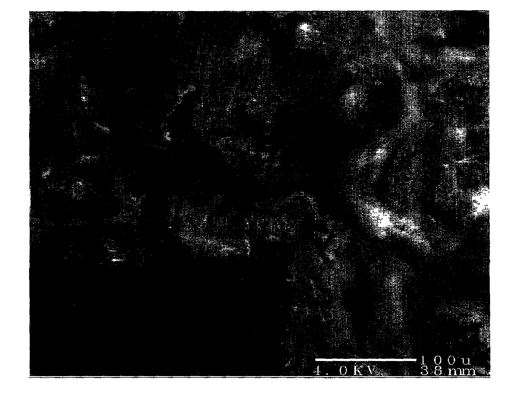
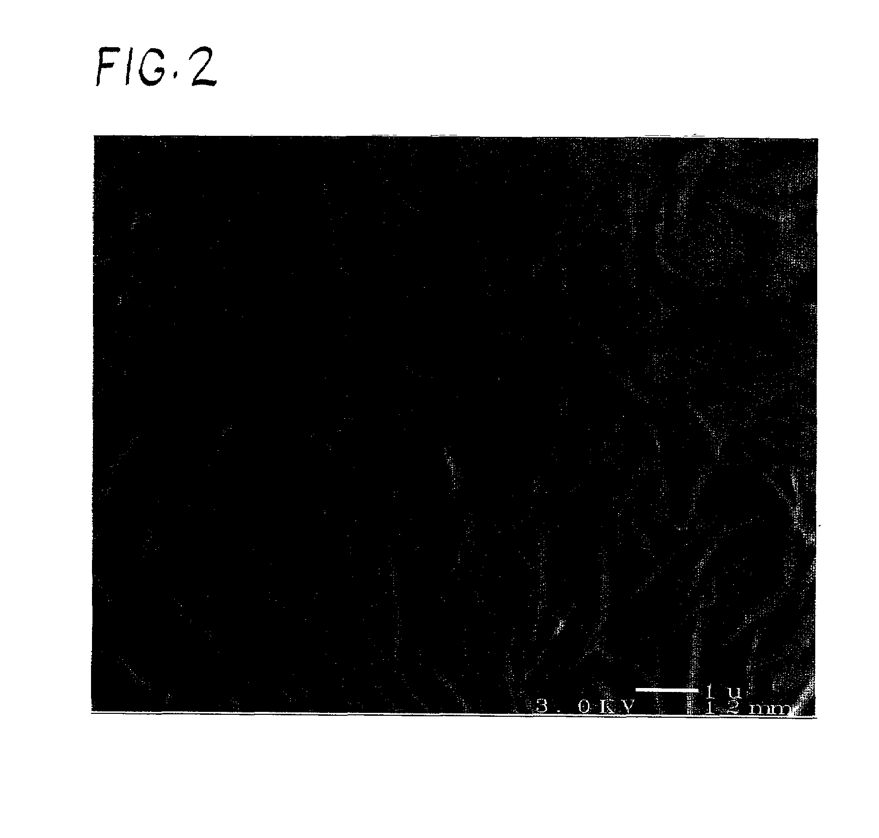
This porous surface structure may contain numerous defect areas or voids due to its plate-like surface structure which lacks a high density.
It is believed that the low density and porous structure may lead to surface flaws in the hydroxyapatite coating during use in vivo and lead to the problems discussed above.

Method used


Image

  • Electrolytic deposition of coatings for prosthetic metals and alloys
  • Electrolytic deposition of coatings for prosthetic metals and alloys
  • Electrolytic deposition of coatings for prosthetic metals and alloys

Examples


example 1

[0047]In this Example, a substrate was first electrolytically coated with brushite and subsequently electrolytically coated with a layer of chitosan. After the chitosan was deposited, the brushite was converted to hydroxyapatite to produce a substrate having deposited thereon a composite coating comprising hydroxyapatite and chitosan.

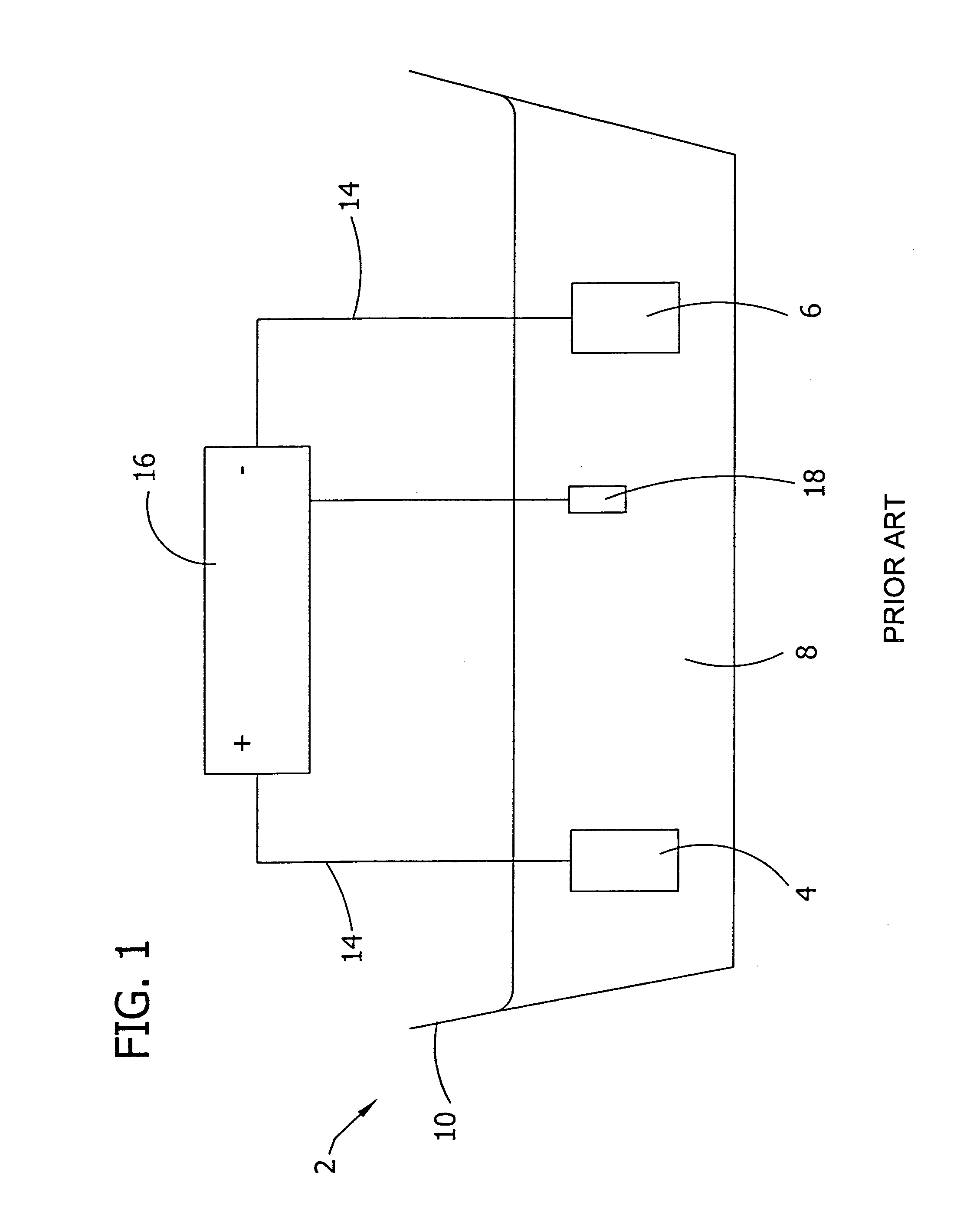
[0048]An electrolytic apparatus was set up comprising a potentionstat / galvanostat (PAR Model 273) to control to current density between the anode and cathode during coating, an anode made of a platinum basket, and a cathode comprising titanium (99.7%) for depositing a bio-compatible layer thereon. Prior to insertion into the electrolytic apparatus, the cathode was subjected to a grinding process comprising coarse grinding the cathode surface with sandpaper (600 grit) followed by double polishing the surface with alumina (3.0 microns size followed by 0.3 microns size.) After the grinding / polishing, the cathode was cleaned by scrubbing the surface with a ...

example 2

[0054]In this Example, a substrate had simultaneously electrolytically deposited thereon a composite coating of brushite and chitosan. After the brushite / chitosan composite coating was deposited on the substrate, the substrate was subjected to a process to convert the brushite present in the composite coating to hydroxyapatite to form a composite coating comprised of hydroxyapatite and chitosan.

[0055]An electrolytic apparatus was set up comprising a potentionstat / galvanostat (PAR Model 273) to control to current density during coating deposition, an anode made of a platinum basket, and a cathode made of titanium (99.7%) for depositing a bio-compatible layer thereon. Prior to insertion into the electrolytic apparatus, the cathode was subjected to a grinding process comprising coarse grinding the cathode surface with sandpaper (600 grit) followed by double polishing the surface with alumina (3.0 microns size followed by 0.3 microns size.) After the grinding / polishing, the cathode was ...


PUM

PropertyMeasurementUnit
Temperatureaaaaaaaaaa
Fractionaaaaaaaaaa

Abstract

An article coated with an electrolytically deposited bio-compatible composite layer useful as an internal prosthetic device is disclosed. The bio-compatible composite coating that is electrolytically deposited onto the article comprises hydroxyapatite and chitosan. The introduction of chitosan into the crystal matrix of brushite / hydroxyapatite significantly improves the adhesive and chemical and mechanical stability properties of the coating.

Description

[0001]This Application claims the benefit of Provisional Application Ser. No. 60 / 258,897 filed on Dec. 28, 2000.BACKGROUND OF THE INVENTION[0002]The present invention relates to articles useful as prosthetic devices coated with an electrolytically deposited bio-compatible composite layer. More particularly, the present invention relates to a prosthetic device coated with an electrolytically deposited bio-compatible composite layer comprising hydroxyapatite and chitosan. The present invention also relates to a process for electrolytically depositing a bio-compatible composite layer on an article.[0003]When a bone is fractured or otherwise severely damaged, it may be necessary to fixate all or a part of the bone to an internal metallic transplant support structure for stabilization and to facilitate proper healing. One problem encountered with the incorporation of metallic support structures in vivo is the inability of the structure to become fixated with, and attached to, natural bon...

Claims


Application Information

Patent Timeline
IPC IPC(8): C25D5/10C23C28/00C25D11/18C25D9/00C25D9/02A61B17/68A61F2/00A61F2/30A61L27/28
CPCA61B17/68A61L27/28C25D9/02A61F2/30767Y10T428/265A61F2/3094A61F2002/30929A61F2310/00023A61F2310/00029A61F2310/00047A61F2310/00053A61F2310/00059A61F2310/00089A61F2310/00095A61F2310/00101A61F2310/00119A61F2310/00125A61F2310/00131A61F2310/00137A61F2310/00574A61F2310/00796A61F2310/00856Y10T428/31678Y10T428/31504
Inventor REDEPENNING, JODY G.
Owner BOARD OF RGT UNIV OF NEBRASKA
Learn More