
Semiconductor device with multilayer conductive structure formed on a semiconductor substrate

a semiconductor substrate and conductive structure technology, applied in the direction of semiconductor devices, semiconductor/solid-state device details, electrical apparatus, etc., can solve the problems of weak adhesion between the adjacent conductive film and the insulating film, voids and disconnections due to migration, and defects such as cracks in the adjacent film, so as to improve adhesion and high stress , the effect of high stress

Inactive Publication Date: 2006-03-14
LONGITUDE SEMICON S A R L
View PDF18 Cites 3 Cited by
  • Summary
  • Abstract
  • Description
  • Claims
  • Application Information

AI Technical Summary

Benefits of technology

[0006]In the manufacture of semiconductor devices which are finely patterned for higher integration, since there are cases where chemical mechanical polishing (CMP) is employed as a technique for effecting planarization, it is important to improve adhesion between the respective films formed. However, if rhodium (Rh), ruthenium (Ru), iridium (Ir), or osmium (Os) is used as the material of the adjacent conductive film in the copper (Cu) wiring, the adhesion between copper (Cu) and the adjacent conductive film improves, but there is a problem in that the adhesion between the adjacent conductive film and the insulating film is weak. Further, rhodium (Rh), ruthenium (Ru), iridium (Ir), and osmium (Os) are liable to produce high stress during film formation, possibly causing defects such as cracks to occur in an adjacent film. Furthermore, with the semiconductor devices which are finely patterned for higher integration, the wiring width becomes narrow, so that there is a problem in that voids and disconnections due to migration are likely to occur.
[0007]A first object of the invention is to provide a highly reliable semiconductor device. A second object of the invention is to provide a semiconductor device having a wiring structure whose yield is high. A third object of the invention is to provide a semiconductor device having a multilayer structure in which adhesive fracture is difficult to occur by the use of highly adhesive adjacent conductive film materials for both a main conductive film forming the wiring and an insulating film. Further, a fourth object of the invention is to provide a semiconductor device having a multilayer structure in which defects such as cracks are difficult to occur. Furthermore, a fifth object of the invention is to provide a semiconductor device in which voids and disconnections due to migration are difficult to occur.
[0011]The present inventors ascertained that the adhesivity between the first conductive film and the insulating film improves in a case where the bond energy between this added element and silicon (Si) is not less than 1.9 times that of the main constituent element of the first conductive film and silicon (Si). Nevertheless, if the difference between the atomic radius of the added element and the atomic radius of the main constituent element such as rhodium (Rh), ruthenium (Ru), iridium (Ir), osmium (Os), and platinum (Pt) becomes not less than 10%, the atomic arrangement of the first conductive film becomes disarrayed, so that the adhesion between the first conductive film and the copper (Cu) film becomes weak. Accordingly, an added element becomes effective in which the difference between the atomic radius of the added element and the atomic radius of the main constituent element of the first conductive film is not more than 10%, and whose bond energy with silicon (Si) is not less than 1.9 times the bond energy between the main constituent element of the first conductive film and silicon (Si). It was ascertained that palladium (Pd), cobalt (Co), nickel (Ni), and titanium (Ti) are effective as added elements which satisfy these conditions. Further, it was ascertained that the inclusion of such added elements is effective in reducing the internal stress in the first conductive film.
[0012]Furthermore, the present inventors ascertained that in a case where rhodium (Rh), ruthenium (Ru), iridium (Ir), osmium (Os), and platinum (Pt) whose lattice mismatching A and B with copper (Cu) are small enough to satisfy the aforementioned inequality {A+B×(ap / bp)}<13% and which have melting points not less than 1.4 times that of copper (Cu) are used as the main constituent elements of the conductive film adjacent to the copper (Cu) film, the diffusion of the copper (Cu) atoms is suppressed, and migration resistance improves.

Problems solved by technology

However, if rhodium (Rh), ruthenium (Ru), iridium (Ir), or osmium (Os) is used as the material of the adjacent conductive film in the copper (Cu) wiring, the adhesion between copper (Cu) and the adjacent conductive film improves, but there is a problem in that the adhesion between the adjacent conductive film and the insulating film is weak.
Further, rhodium (Rh), ruthenium (Ru), iridium (Ir), and osmium (Os) are liable to produce high stress during film formation, possibly causing defects such as cracks to occur in an adjacent film.
Furthermore, with the semiconductor devices which are finely patterned for higher integration, the wiring width becomes narrow, so that there is a problem in that voids and disconnections due to migration are likely to occur.

Method used


Image

  • Semiconductor device with multilayer conductive structure formed on a semiconductor substrate
  • Semiconductor device with multilayer conductive structure formed on a semiconductor substrate
  • Semiconductor device with multilayer conductive structure formed on a semiconductor substrate

Examples


Embodiment Construction

[0031]Hereafter, a more detailed description will be given for carrying out the invention through the various embodiments shown in the drawings.

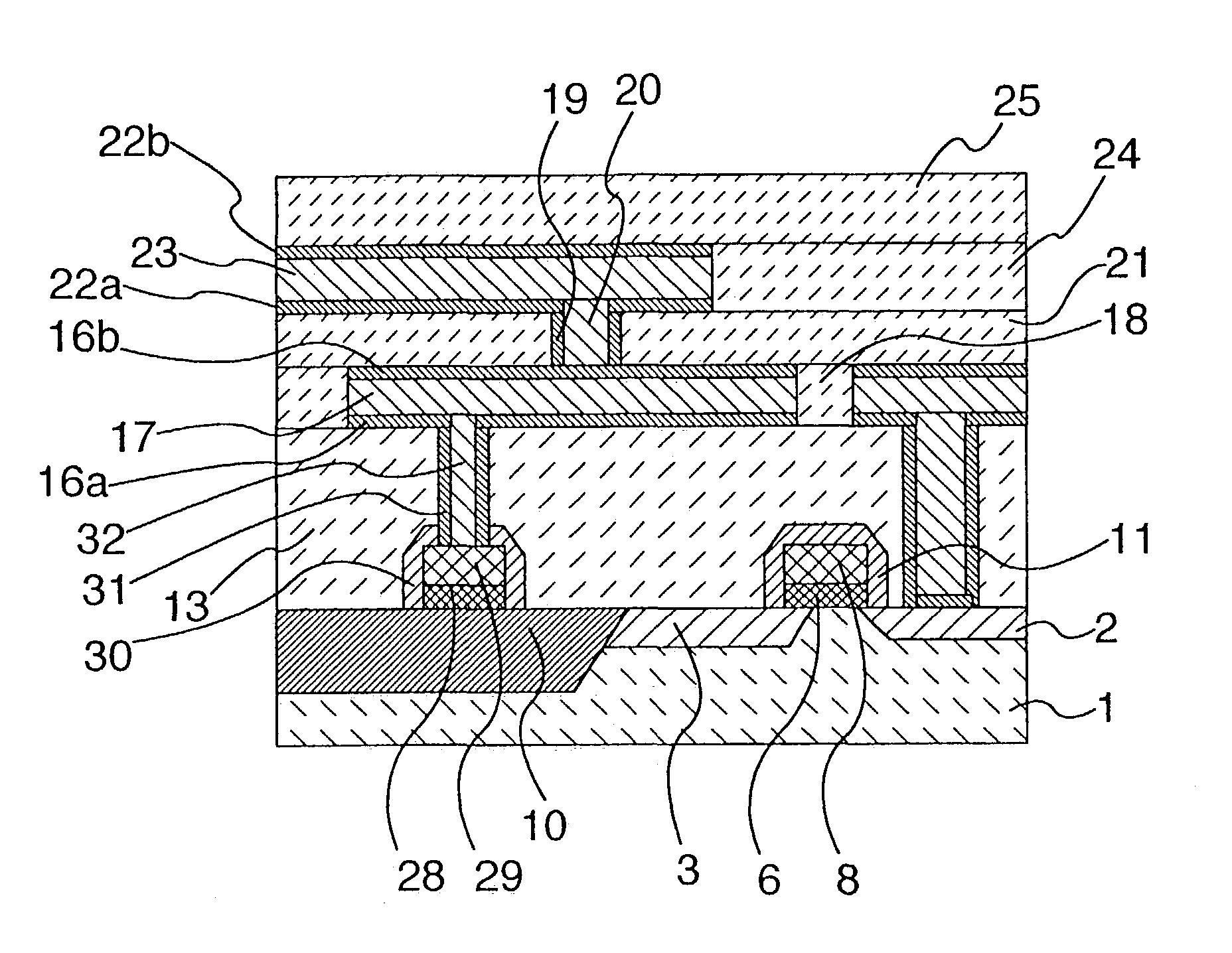
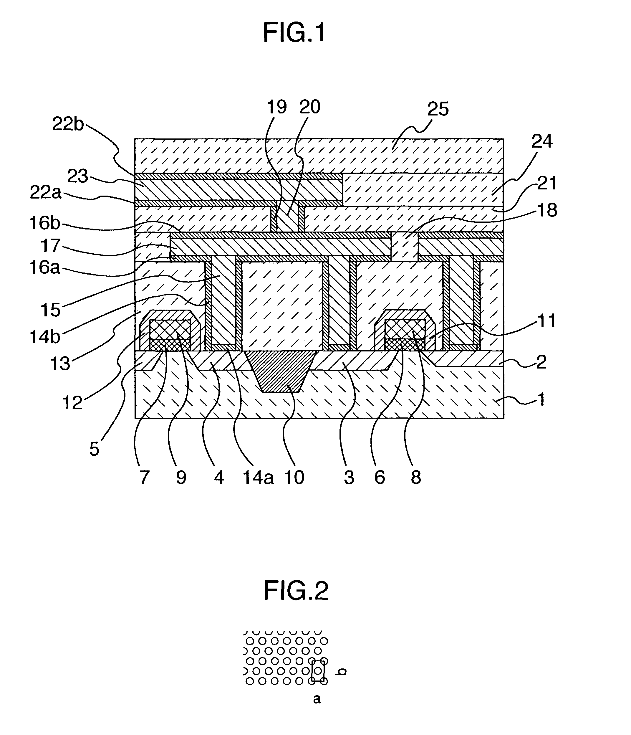
[0032]First, a cross-sectional structure of principal portions of a semiconductor device in accordance with a first embodiment of the invention is shown in FIG. 1. As shown in FIG. 1, in the semiconductor device of this embodiment, diffusion layers 2, 3, 4, and 5 are formed on a silicon substrate 1, and gate insulating films 6 and 7 and gate electrodes 8 and 9 are formed thereon, thereby forming a MOS transistor. The gate insulating films 6 and 7 are, for example, silicon dioxide films or silicon nitride films, while the gate electrodes 8 and 9 are, for example, polycrystalline silicon films, metal thin films, or metal silicide films, or a laminated structure thereof. The MOS transistor is separated by a device separating film 10 formed of, for example, a silicon dioxide film. Insulating films 11 and 12, which are formed of, for example, sil...


PUM


Abstract

A highly reliable semiconductor device having a multilayer structure including an insulating film, an adjacent conductive film, and a main conductive film in which adhesive fractures, voids and disconnections are unlikely to occur. Regarding main constituent elements of the adjacent conductive film and the main conductive film, lattice mismatching is made small, the melting point the adjacent conductive film is set to be not less than 1.4 times that of the main constituent element of the main conductive film, the adjacent conductive film contains at least one different kind of element, the difference between the atomic radius of an added element and that the atomic radius the adjacent conductive film is set to be not more than 10%, and / or bond energy between the added element and silicon (Si) is not less than 1.9 times that of the main constituent element of the adjacent conductive film and silicon (Si).

Description

[0001]This application is a continuation of U.S. application Ser. No. 09 / 787,528, filed Jun. 26, 2002, now U.S. Pat. No. 6,624,513 which is a Section 371 of International Application PCT / JP00 / 00072, filed Jan. 13, 2000, and the entire disclosures of which are hereby incorporated by reference.BACKGROUND OF THE INVENTION[0002]1. Field of the Invention[0003]The present invention relates to a semiconductor device and, more particularly, to a semiconductor device whose wiring structure is formed by a multilayer structure.[0004]2. Prior Art[0005]In conjunction with trends toward higher integration and higher speed of semiconductor devices in recent years, the copper (Cu) wiring, which has a lower electrical resistance than conventional aluminum (Al) wiring, has been introduced. However, if copper (Cu) atoms are diffused and enter a silicon (Si) substrate or an insulating film, there is a possibility of deteriorating the device characteristics, so that an adjacent conductive film (first co...

Claims


Application Information

Patent Timeline
IPC IPC(8): H01L23/532H01L23/52H01L21/3205H01L21/768H01L23/48H01L29/40
CPCH01L21/32051H01L21/76843H01L21/76844H01L21/76846H01L23/53238H01L21/76852H01L21/76877H01L23/53233H01L21/7685H01L2924/0002H01L2924/00H01L21/768
Inventor IWASAKI, TOMIOMIURA, HIDEOASANO, ISAMU
Owner LONGITUDE SEMICON S A R L
Learn More