
Long life thin film battery and method therefor

a thin film, battery technology, applied in the field of microelectronics, can solve the problems of difficult to obtain barrier materials, difficult to maintain, and difficult to achieve liquid electrolytes, etc., and achieve the effect of increasing the life of the battery

Inactive Publication Date: 2006-02-07
OAK RIDGE MICRO ENERGY
View PDF25 Cites 155 Cited by
  • Summary
  • Abstract
  • Description
  • Claims
  • Application Information

AI Technical Summary

Benefits of technology

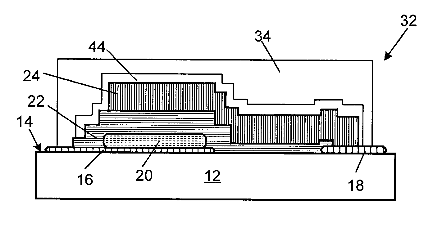
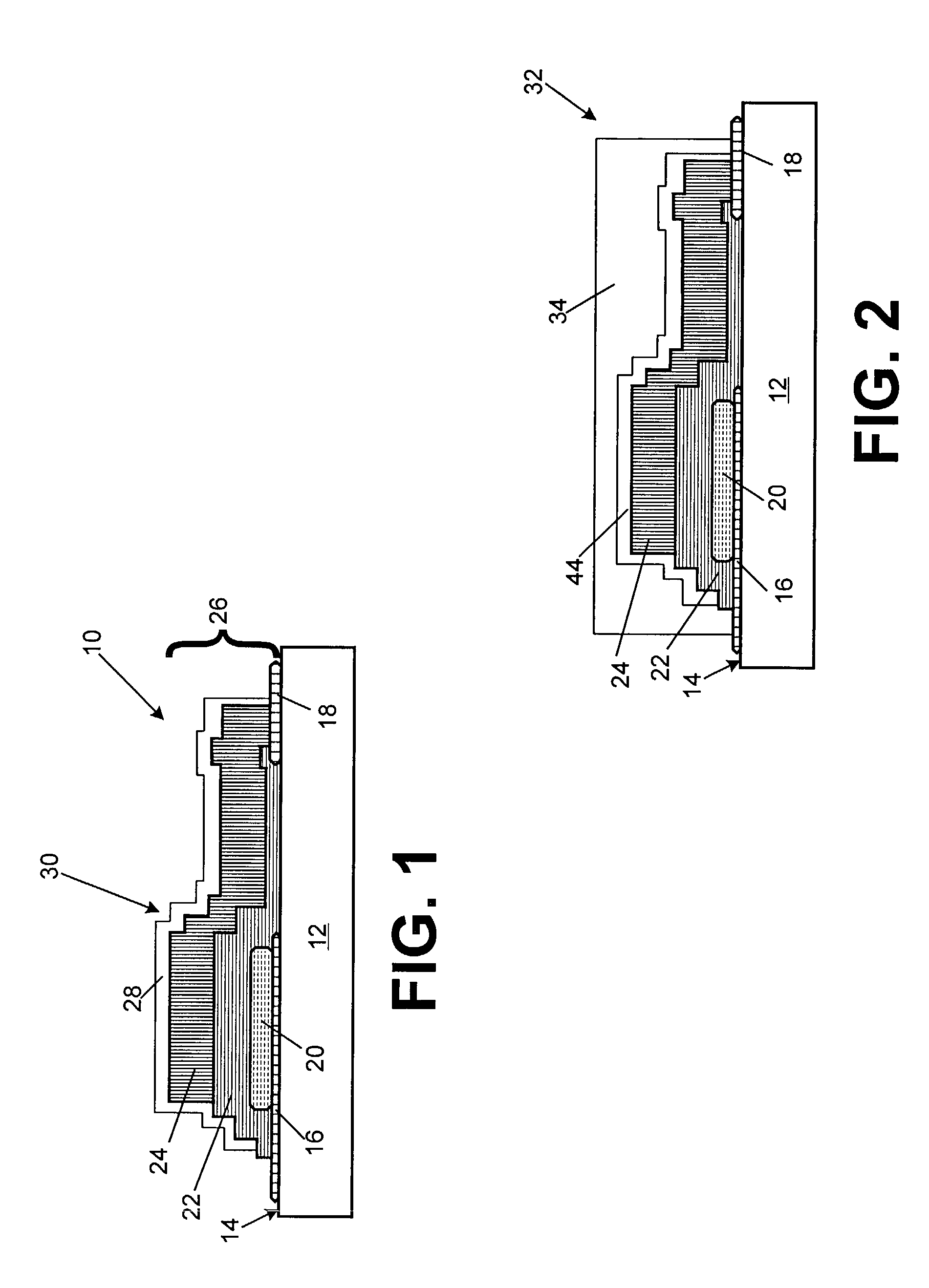
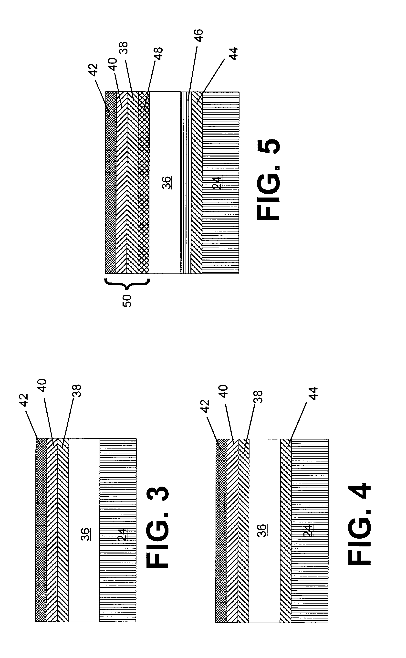
[0009]An important advantage of the invention is that thin-film batteries containing the planarization layer and one or more barrier layers are expected to obtain a life approaching 20 years. Without wishing to be bound by theory, it is believed that a key component contributing to the increased life of the battery is the provision of a planarization layer on the thin film battery prior to depositing the one or more barrier layers on the battery. The planarization layer is preferably applied to the thin film battery so that it is relatively smooth and substantially planar. “Relatively smooth” means having a surface roughness of no more than about 1.0 nanometers root mean square (RMS) “Substantially planar” means having a flatness of no more than about 0.005 cm / inch, that is, the deviation in height per linear inch travel over the surface of the planarization layer is no more than about 0.005 cm.
is that thin-film batteries containing the planarization layer and one or more barrier layers are expected to obtain a life approaching 20 years. Without wishing to be bound by theory, it is believed that a key component contributing to the increased life of the battery is the provision of a planarization layer on the thin film battery prior to depositing the one or more barrier layers on the battery. The planarization layer is preferably applied to the thin film battery so that it is relatively smooth and substantially planar. “Relatively smooth” means having a surface roughness of no more than about 1.0 nanometers root mean square (RMS) “Substantially planar” means having a flatness of no more than about 0.005 cm / inch, that is, the deviation in height per linear inch travel over the surface of the planarization layer is no more than about 0.005 cm.

Problems solved by technology

Liquid electrolytes pose leakage problems and are often highly corrosive.
One of the challenges for thin film battery manufacturers is to provide a thin film battery that will have a life of up to 20 years.
Such a life is particularly difficult to obtain with thin film batteries containing anode materials which are highly reactive with oxygen and / or water or water vapor.
However, such barrier materials have met with limited success.

Method used


Image

  • Long life thin film battery and method therefor
  • Long life thin film battery and method therefor
  • Long life thin film battery and method therefor

Examples


Embodiment Construction

[0016]As set forth above, the invention provides an improved thin-film battery that is expected to have a life of up to about 20 years. The extended life expectancy is provided by a unique thin film battery construction technique. The technique is particularly applicable to extending the life of thin film batteries that contain an anode reactive with oxygen and / or water or water vapor, such as, for example, a lithium anode or lithium ion containing anode. It is well known that lithium is a highly reactive material. On exposure to moist or dry air, lithium can undergo the following reactions:

2Li+H2O+½O2=2LiOH  (I)

2Li+½O2=Li2O  (II)

[0017]Thin film battery lifetime is determined by the time the capacity of the battery decreases to 80% of its rated value. In order to understand the requirements of a protective barrier coating to prevent reaction of the battery components, especially the anode, with oxygen or water on exposure to air, we consider the example of a thin film battery with a...


PUM


Abstract

A thin film battery including an anode layer, a cathode layer and a solid electrolyte layer. The battery also includes, a planarization layer applied to the thin film battery. The planarization layer has a surface roughness of no more than about 1.0 nanometers root mean square and a flatness no larger than about 0.005 cm / inch. A barrier layer is applied to the planarization layer. The barrier layer is provided by one or more layers of material selected from the group consisting of polymeric materials, metals and ceramic materials. The planarization layer and barrier layer are sufficient to reduce oxygen flux through the barrier layer to the anode layer to no more than about 1.6 μmol / m2-day, and H2O flux through the barrier layer to the anode layer to less than about 3.3 μmol / m2-day thereby improving the life of the thin film battery.

Description

[0001]The invention relates to thin film batteries and in particular to improved, long-life thin film batteries and methods for making long-life thin film batteries.BACKGROUND OF THE INVENTION[0002]Thin-film rechargeable batteries have numerous applications in the field of microelectronics. For example, thin-film batteries provide active or standby power for microelectronic devices and circuits. Active power sources of the thin-film battery type are used, for example, in implantable medical devices, remote sensors, miniature transmitters, smart cards, and MEMS devices. Standby power sources of the thin-film battery type are used, for example, in PCMCIA cards and other types of CMOS-SRAM memory devices.[0003]In a thin-film battery, a chemical reaction takes place between an anode and cathode by interaction of the anode and cathode through an electrolyte. The attractiveness of thin-film batteries over conventional batteries is that the electrolyte is a substantially solid or non-flowa...

Claims


Application Information

Patent Timeline
IPC IPC(8): H01M6/12H01M2/00H01M6/46H01M50/11H01M50/117H01M50/119H01M50/121H01M50/122H01M50/126H01M50/131H01M50/141
CPCH01M2/0207H01M2/0275H01M2/0277H01M6/12H01M6/40H01M2/0285H01M2002/0297H01M2/0292H01M50/131H01M50/124H01M50/1245H01M50/126H01M50/141H01M50/121H01M50/11H01M50/117H01M50/119H01M50/122
Inventor BATES, JOHN B.
Owner OAK RIDGE MICRO ENERGY
Learn More