Exhaust gas treating device

Inactive Publication Date: 2005-11-29
EBARA CORP
View PDF36 Cites 47 Cited by
  • Summary
  • Abstract
  • Description
  • Claims
  • Application Information

AI Technical Summary

Benefits of technology

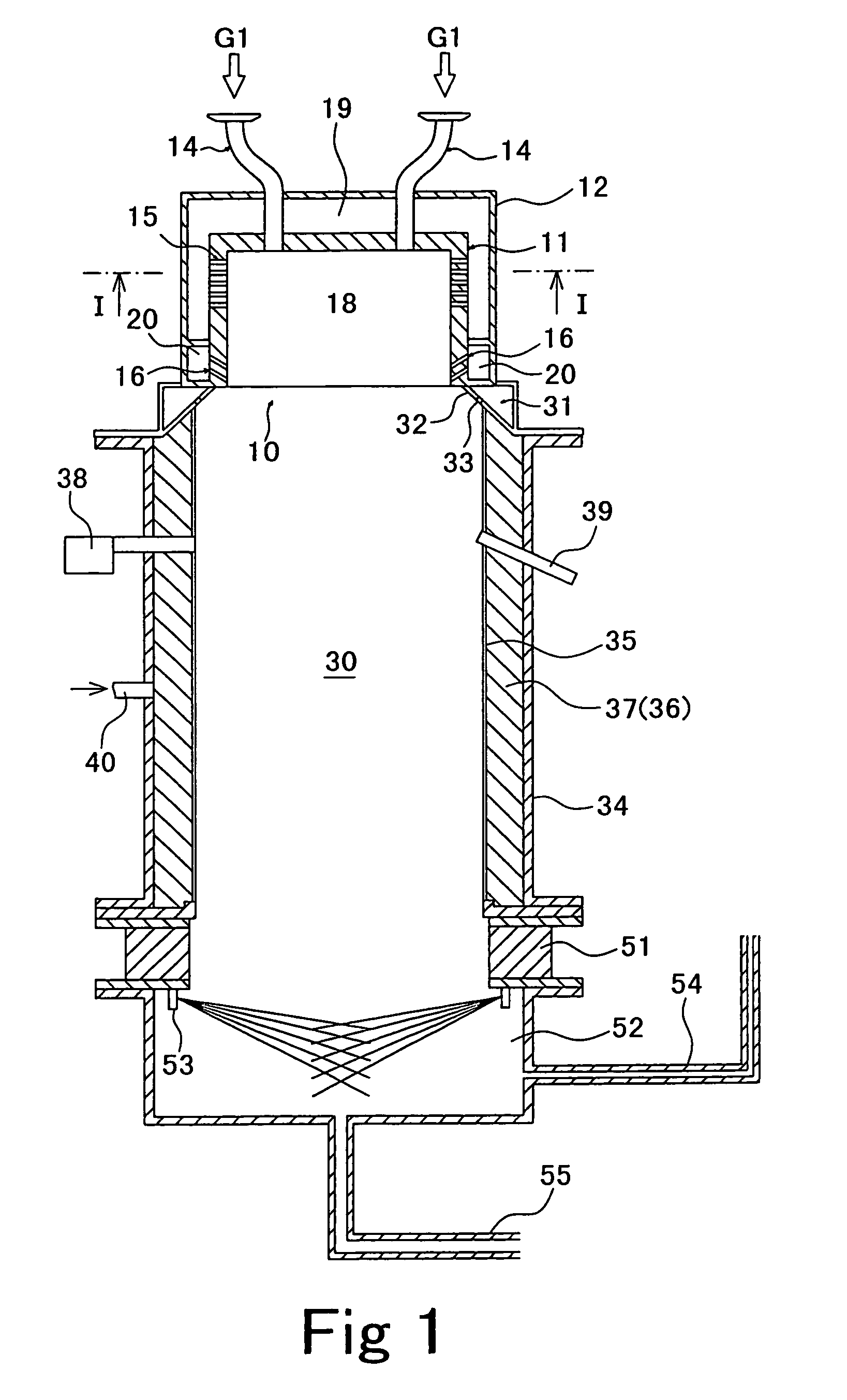
[0019]The present invention provides a waste gas treatment system having a burner part and a combustion chamber provided at the downstream side of the burner part, wherein combustion flames are formed from the burner part toward the 
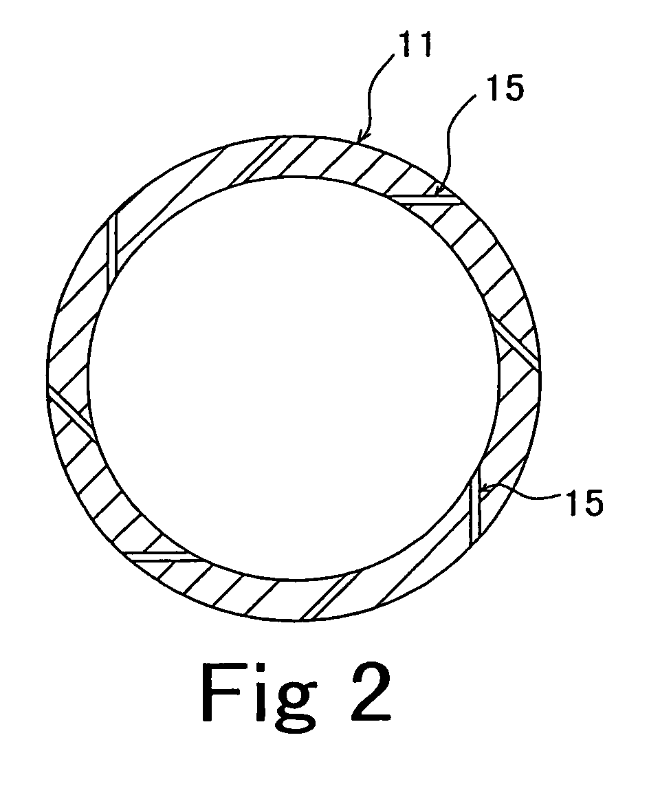
combustion chamber. A waste gas is introduced into the combustion flames, thereby oxidatively decomposing the waste gas. In the waste gas treatment system, the combustion chamber is formed from an inner wall made of a fiber-reinforced ceramic material. Therefore, the wear of the inner wall due to heat and corrosion is minimized, and thermal stress cracking is also reduced. Consequently, the lifetime of the system increases, and the cost of equipment and the availability factor can be improved. In addition, because the inner wall exhibits no catalytic effect, the formation of thermal NOx is suppressed, and it is possible to achieve environmental preservation and to simplify the treatment equipment. In addition, because the space between the inner wall and the outer vessel is maintained under a purge gas atmosphere of higher pressure than the pressure in the combustion chamber, it is possible to prevent hazardous gases in the combustion chamber from leaking to the outside.
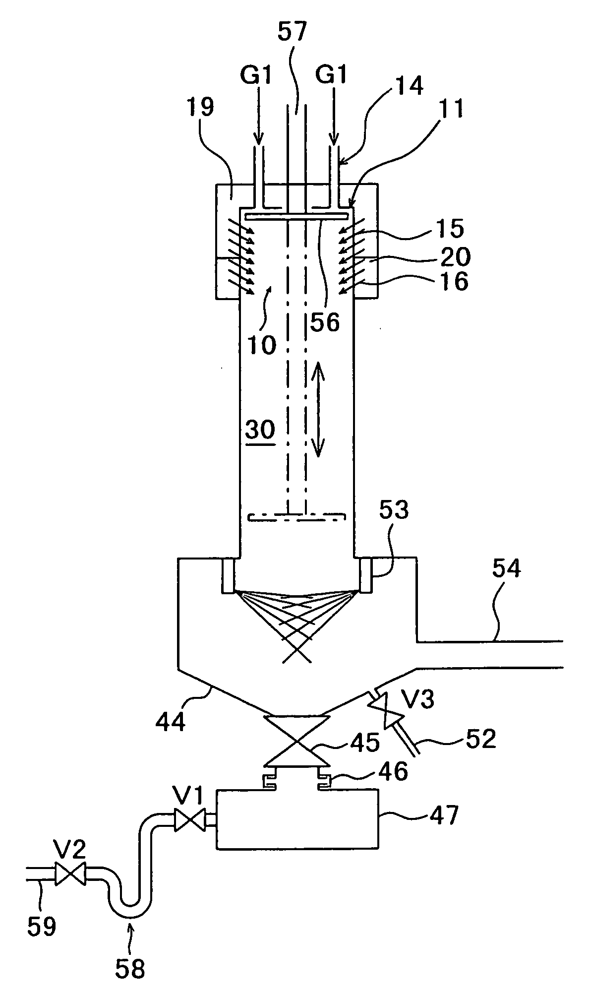
[0020]In addition, there is provided a waste gas treatment system wherein a burner part has a cylindrical member which is closed at the top thereof and has an opening at the bottom thereof. The cylindrical member has a waste gas inlet in the top thereof and an air nozzle at a predetermined position on the side wall thereof. The cylindrical member further has an auxiliary burning gas nozzle in the side wall in the vicinity of the opening. A waste gas introduced from the waste gas inlet and air blown off from the air nozzle are mixed together, and an auxiliary burning gas blown off from the auxiliary burning gas nozzle is ignited to form combustion flames downward below the opening. In addition, a cooling means is provided to cool an auxiliary burning gas inlet part for introducing a fuel gas into the auxiliary burning gas nozzle. Accordingly, even when the auxiliary burning gas inlet part is heated by flames, the rise in temperature is suppressed below the ignition point of the auxiliary burning gas. Therefore, there is no danger that the auxiliary burning gas may explode.
[0021]In addition, there is provided a waste gas treatment system that is provided with a dust removing means for removing dust from the inner wall of the burner part and / or the inner wall of the combustion chamber or for preventing adhesion of dust thereto, thereby allowing the waste gas treatment system to be operated for a long period of time.
[0022]In addition, there is provided a dust remover for removing dust from the inner wall of piping through which a gas containing a large amount of dust flows. The dust remover includes a scraping mechanism placed in the piping. The scraping mechanism has rod-shaped scraping member secured to a main shaft to extend in the longitudinal direction of the piping. The dust remover further includes a support mechanism for supporting the main shaft of the scraping mechanism so that the scraping member moves in the inner peripheral direction in contact with the inner surface of the piping or with a slight gap therebetween, and a driving mechanism for continuously or periodically oscillating or rotating the scraping mechanism about the main shaft. Thus, a cleaning gas is supplied from the outside of the piping through the hollow portions of the main shaft and the scraping member and blown off from the distal end of the scraping member or from a multiplicity of holes or slits in the surface thereof. Consequently, it is possible to remove dust from an area in the piping that cannot be reached by the scraping member. In addition, it becomes possible to remove dust attached to the scraping mechanism itself.
[0025]In addition, there is provided a waste gas treatment system having a burner part, a combustion chamber provided at the downstream side of the burner part, and a combustion gas cooling section provided at the downstream side of the combustion chamber. The burner part, the combustion chamber and the combustion gas cooling section are provided integrally. The burner part is provided with a waste gas inlet for introducing a waste gas and an air nozzle for injecting air to generate a swirling flow. The combustion gas cooling section is provided with a liquid spray nozzle for spraying a liquid for cooling the waste gas flowing in from the combustion chamber and for capturing dust contained in the waste gas, an exhaust pipe for discharging the waste gas, and a drain pipe for draining the liquid sprayed from the liquid spray nozzle. With the waste gas treatment system thus arranged, the waste gas can be decomposition-treated, and dust, HCl and HF in the waste gas introduced from the waste gas inlet can be efficiently captured and absorbed in the liquid sprayed from the spray nozzle.

Problems solved by technology

Further, waste gases containing scarcely decomposable, global warming gases (PFCs) are also likely to generate dust when treated by combustion.
Such waste gases cannot be emitted into the atmosphere as they are because they would have adverse effects upon the human body and change the global environment.
The greater part of the running cost of the system is the cost for consumption of the fuel gas and the oxidizing agent.
To use these techniques, decomposition treatment of fluorocarbon-containing gases is carried out under application of an enormous amount of energy for heating and plasma generation in decomposition treatment equipment having a complicated control mechanism for controlling a heating device, e.g., a heater, a plasma generator, a safety device, etc.
Therefore, the furnace body 106 wears out rapidly and cannot withstand long-term operation.
In particular, when a halogen-containing gas is decomposition-treated by this system, the furnace body is etched or corroded under high temperature by a halogen gas (HCl, HF, etc.) produced after the treatment reaction and hence wears out rapidly.
This causes the cost of equipment to increase.
Further, when the metallic furnace body wears out, there is a danger that wear may develop in the surrounding structures (the thermal insulator, the water-cooled vessel, etc.).
This causes the availability for use of the equipment to be reduced markedly and gives rise to an increase in the running cost.
Consequently, the equipment cannot be made compact in size.
Therefore, there is a danger that the auxiliary burning gas G2 supplied to the burner part 101 may ignite and explode.
Such dust flows, together with waste gas, and adheres to the inner wall surfaces of piping and so forth, causing the exhaust pressure loss to increase.
This method involves the problem that if the position of the nozzle is away from where dust may adhere, the dust removal effect is lessened.
If a large amount of cleaning gas is supplied to maintain the dust removal effect, the cost of cleaning gas increases.
Further, the cost of cleaning gas is increasing, and it is necessary to increase the size of equipment such as a duct for exhausting the gas discharged from the pretreatment system in a building to the outside of the building.

Method used


Image

  • Exhaust gas treating device
  • Exhaust gas treating device
  • Exhaust gas treating device

Examples


Embodiment Construction

[0054]FIGS. 1 and 2 are diagrams showing the arrangement of a waste gas combustor in the waste gas treatment system according to the present invention. FIG. 1 is a vertical sectional view, and FIG. 2 is a sectional view taken along the line I—I in FIG. 1. The waste gas combustor is formed in the shape of a cylindrical closed vessel as a whole. The waste gas combustor has a burner part 10 in an upper stage and a combustion chamber (combustion reaction part) 30 in an intermediate stage. The waste gas combustor has a cooling part 51 and a discharge part 52 in a lower stage. As a cooling medium in the cooling part 51, for example, a liquid, e.g. water, or a gas, e.g., air, is used.

[0055]The burner part 10 has a cylindrical member 11 forming a flame stabilizing portion 18 opening toward the combustion chamber 30. The burner part 10 further has an outer cylinder 12 surrounding the cylindrical member 11 with a predetermined space therebetween. Between the cylindrical member 11 and the oute...


PUM


Abstract

A waste gas treatment system having a burner part and a combustion chamber provided at a downstream side of the burner part. Combustion flames are formed from the burner part toward the combustion chamber, and a waste gas is introduced into the combustion flames, thereby oxidatively decomposing the waste gas. The combustion chamber is formed from an inner wall made of a fiber-reinforced ceramic material. Therefore, the wear of the inner wall due to heat and corrosion is minimized, and thermal stress cracking is also reduced. Consequently, the lifetime of the system increases, and the cost of equipment and the availability factor can be improved. In addition, because the inner wall exhibits no catalytic effect, the formation of thermal NOx is suppressed, and it is possible to achieve environmental preservation and to simplify the treatment equipment.

Description

TECHNICAL FIELD[0001]The present invention relates to a waste gas treatment system for treating a waste gas likely to generate dust when it is treated by combustion. For example, the present invention relates to a combustion type waste gas treatment system for combustion-treating hazardous and combustible waste gases containing silane gas (SiH4) or a halogen-containing gas (NF3, ClF3, SF6, CHF3, C2F6, CF4, etc.) or hardly decomposable waste gases.BACKGROUND ART[0002]Waste gases that are likely to generate dust when treated by combustion include those which contain hazardous and combustible gases, e.g., silane (SiH4) and disilane (Si2H6) discharged from semiconductor manufacturing systems or liquid crystal panel manufacturing systems. Further, waste gases containing scarcely decomposable, global warming gases (PFCs) are also likely to generate dust when treated by combustion. Such waste gases cannot be emitted into the atmosphere as they are because they would have adverse effects up...

Claims


Application Information

Patent Timeline
IPC IPC(8): B01D53/46B01D53/68B01D53/70F23G5/32F23G7/06F23J3/02F23M5/08
CPCB01D53/46B01D53/68B01D53/70F23G5/32F23G7/06F23G7/065F23J3/02F23M5/085B01D2257/00B01D2257/20B01D2257/204B01D2257/206B01D2257/2064B01D2257/2066F23J2219/70F23M2900/05004
Inventor KAWAMURA, KOTARONAKAMURA, RIKIYASHIRAO, YUJITAKEMURA, YOSHIROOKUDA, KAZUTAKATSUJI, TAKESHI
Owner EBARA CORP
Why Eureka
Try Eureka