Catalytic metal plate

Inactive Publication Date: 2005-07-26
ENGELHARD CORP
View PDF78 Cites 45 Cited by
  • Summary
  • Abstract
  • Description
  • Claims
  • Application Information

AI Technical Summary

Benefits of technology

[0032]The present invention is directed to a catalytic metal article and related methods of preparation and use. The article comprises a metal substrate which is preferably in the form of a metallic plate. The metallic plate preferably comprises up to 20.0 weight percent aluminum. A preferred metal is a steel composition comprising iron, aluminum and preferably chromium. The metal substrate has a substrate surface. For the purpose of the present invention, the term substrate surface is considered to be the surface of the metal substrate and can include a thin layer which can be up to 10 micrometers thick or more which is derived from metal within the metal substrate which defuses to the surface, or from metal which is plated or clad onto the surface. The metal of the substrate surface is preferably in a continuous layer up to about 5 micrometers thick and is preferably selected from aluminum and rare earth metals. The substrate surface metal can be oxidized by calcining in the presence of oxygen in a temperature range of from about 800° to about 1200° C. Preferably the substrate surface comprises alumina in a continuous layer ranging up to 5 micrometers and more preferably 3 micrometers in thickness. The alumina substrate surface enhances adhesion to catalyst compositions which may be deposited thereon. The presence of rare earth oxides enhances the thermal stability at the substrate surface.
[0033]The article comprises a catalyst comprising at least one catalyst layer supported on the substrate surface. The catalyst layer has an outer catalyst layer surface. The catalyst composition comprises at least one catalytically active particulate material. The catalytically active particulate material can be any suitable particulate material and is preferably a refractory oxide compound used to support a catalytically active precious metal component. The catalyst layer preferably comprises at least two and more preferably a plurality of strata. That is each catalyst layer is formed by a plurality of thin catalyst composition coatings. There is an outer catalyst layer surface which comprises agglomerates of the catalytically active particulate material. The agglomerates of the outer catalyst layer preferably have an average diameter of from about 20 to about 200 micrometers. At the outer surface, particularly when the catalyst composition is sprayed from an aqueous slurry, the agglomerates adhere to each other to form peaks. Typically and preferably, the peaks range from about 20 to about 500 micrometers. This forms a rough surface which enhances mass transfer from the gas into the catalyst layer.

Problems solved by technology

Such engines provide a severe environment for a catalytic exhaust treatment apparatus.
This is because in small engines, the exhaust gas contains a high concentration of unburned fuel and unconsumed oxygen.
The harsh vibration and exhaust gas temperature conditions associated with small engines lead to several modes of failure in the exhaust gas catalytic treatment apparatus, including failure of the mounting structure by which a catalyst member is secured in the apparatus and consequential damage or destruction of the catalyst member due to the mechanical vibration and to flow fluctuation of the exhaust gas under high temperature conditions.
The ceramic-like material is subject to cracking and pulverization by excessive vibration.
Although many of these materials suffer from the disadvantage of having a considerably lower BET surface area than activated alumina, that disadvantage tends to be offset by a greater durability of the resulting catalyst.

Method used


Image

  • Catalytic metal plate
  • Catalytic metal plate
  • Catalytic metal plate

Examples


example 1

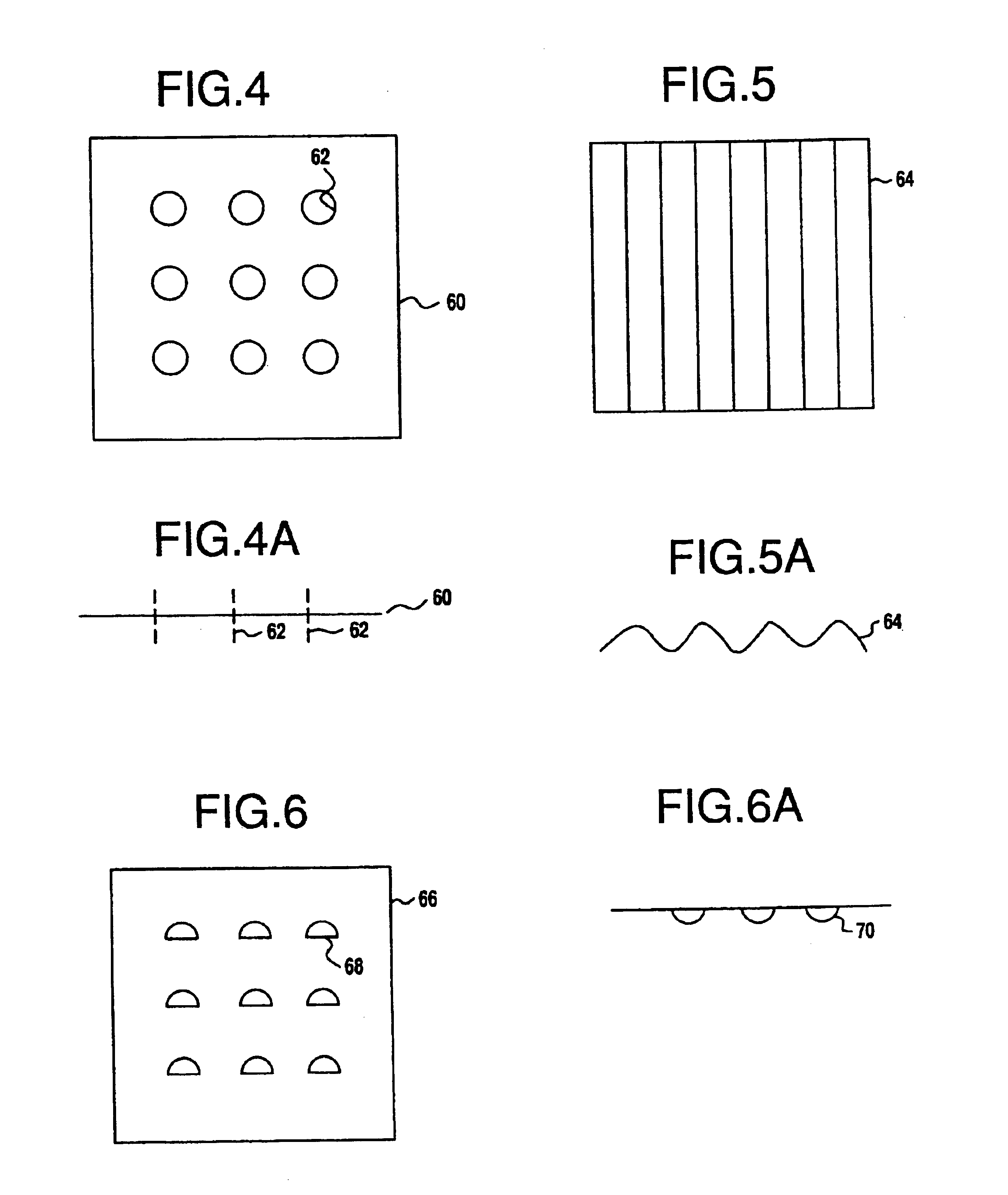
[0177]A catalyst composition was prepared as a tie layer or base coat. This composition was formed into a slurry comprising 35 percent alumina specified to have a particle size of 5 to 100 micrometers and a surface area of 150 m2 / g and 2 weight percent (based on ZrO2) zirconia acetate as a binder with 14 weight percent acetic acid. The slurry was ballmilled for 24 hours to result in a particle size of 90 percent of the particles being less than 4 micrometers when using a Horiba laser particle size analyzer. The design of the metal plate was of the type shown in FIG. 4. The metal plate was 30 mils thick. The surface of the metal plate was roughened by sandblasting using 30 to 100 mesh alumina particles. The metal plate was then heated for 2 hours at 980° C. to form an alumina surface. The composition comprises iron and about 20.4 percent chromium, 5.2 percent aluminum, about 0.20 percent cerium, about 0.078 percent carbon, about 0.20 percent silica, less than. about 0.3 percent manga...

example 2

[0182]A coated metal plate for small engine applications was made using a metal plate made of a steel composition comprising the same composition as in Example 1. The metal plate was pressed into a final shape which is of the type illustrated in FIG. 17. A microphotograph of the clean surface is shown in FIGS. 9A and 9B. The metal plate was first sandblasted using a 30 to 100 mesh alumina to clean the surface and generate a random rough surface. The surface is shown in the microphotograph of FIGS. 10A and 10B. The metal plate was then calcined at 980° C. to generate an alumina bonding layer. A surface analysis by electron dispersive spectrascopy (EDS) indicated that the original metal was mainly iron, chromium and aluminum and the surface composition was not significantly changed by sandblast treatment. Upon heating the surface was mainly covered with aluminum indicating that the alumina inside the metal interior had migrated into the surface to form a protecting and binding layer. ...

example 3

[0185]Two coated metal plate catalyst samples were prepared and engine aged and evaluated. The fresh and aged activities of the samples were found to be satisfactory. Two perforated metal plates of the type shown in FIG. 4 were first treated with a sand blast gun using 30-100 mesh alumina to increase surface roughness. The plates were then calcined at 950° C. for two hours. The plate was cooled to room temperature and a thin coat comprising alumina having a surface area of 150 m3 / g and a particle size of 90 percent of the particles less than 5 micrometers was applied with a paintbrush to form a tie layer. The alumina tie coat was allowed to dry. A bottom layer catalyst coat composition recited below was applied and allowed to dry followed by a top catalytic layer composition as recited below. Plate 1 had a blank weight of 32.84 grams. To this was added 0.353 grams of tie coat, 0.75 grams of a bottom catalytic coat and 1.52 grams of a top catalytic coat resulting in a total addition ...


PUM

PropertyMeasurementUnit
Temperatureaaaaaaaaaa
Timeaaaaaaaaaa

Abstract

The present invention is directed to a catalyzed metallic substrate, such as a metal plate. There is a catalyst layer supported on the substrate surface. The article is useful as part of exhaust systems which can be used with small engines for applications such as motorcycles, lawn mowers, chain saws, weed trimmers and the like. The present invention includes methods to prepare the catalyzed metal substrate and methods of use of the catalyzed substrate.

Description

[0001]This application is a continuation of application Ser. No. 09 / 917,847 filed Jul. 26, 2001, now abandoned, which is a continuation of application Ser. No. 08 / 761,544 filed Dec. 6, 1996, having a Continued Prosecution Application filed Jun. 21, 2000, now abandoned.BACKGROUND OF THE INVENTION[0002]1. Field of the Invention[0003]The present invention relates to a catalytic metal article, and in more specific embodiments a catalytic metal plate and related methods of preparation and use. The article of present invention is useful for the treatment of gases to reduce contaminants contained therein.[0004]2. Discussion of Related Art[0005]The exhaust gases of internal combustion engines, including small engines, are known to contain pollutants such as hydrocarbons, carbon monoxide and nitrogen oxides (NOx) that foul the air.[0006]Small internal combustion engines, usually two-stroke and four-stroke spark ignition engines are used to provide power to a variety of machinery, e.g. gasoli...

Claims


Application Information

Patent Timeline
IPC IPC(8): B01J23/63B01D53/94B01J23/54B01J37/02B01J37/00
CPCB01D53/945B01J23/63B01J37/0225B01J37/0226B01J37/0244Y02T10/22Y10T428/31678Y02T10/12
Inventor HWANG, H. SHINNDETTLING, JOSEPH C.GALLIGAN, MICHAEL P.BROWN, RONALD J.MOONEY, JOHN J.
Owner ENGELHARD CORP
Why Eureka
Try Eureka