
Method for cell patterning

a cell patterning and cell technology, applied in the field of cell patterning, can solve the problems of destroying the cells themselves, requiring clean-room facilities and other complex equipment, and not being readily accessible to most biologists

Inactive Publication Date: 2005-05-17
PRESIDENT & FELLOWS OF HARVARD COLLEGE
View PDF53 Cites 58 Cited by
  • Summary
  • Abstract
  • Description
  • Claims
  • Application Information

AI Technical Summary

Benefits of technology

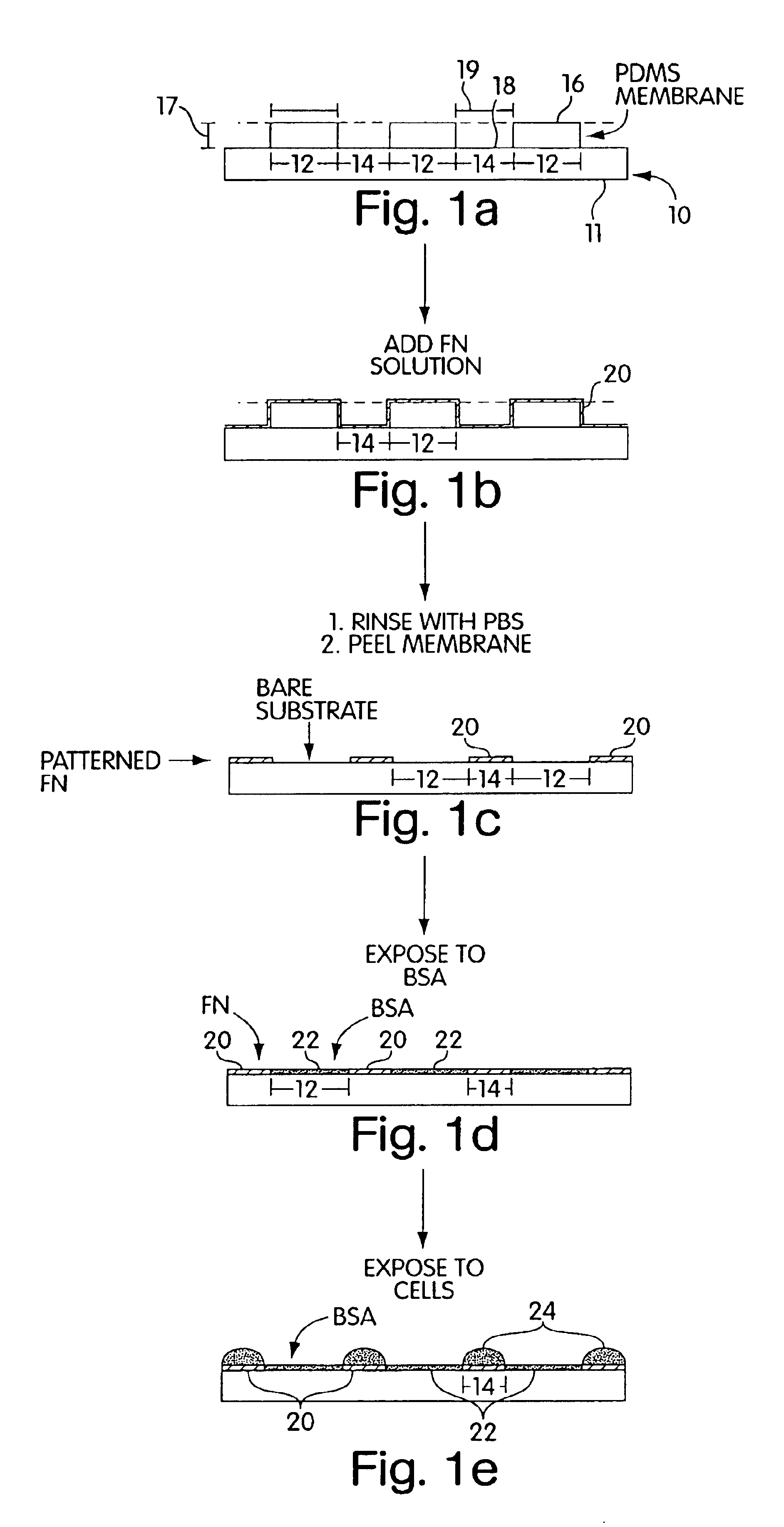
[0012]Another aspect of the present invention provides a method comprising shielding a first portion of a surface of an article with a masking system. The method involves allowing a cell-adhesion promoter to be applied to a second, unshielded portion of the surface of the article while preventing application of the cell-adhesion promoter to the first portion of the surface of the article with the masking system. The method further involves applying a cell to the second portion of the surface.
[0013]Another aspect of the present invention provides a method for patterning cells comprising shielding a first portion of a surface of an article with a polymeric masking system. The method involves applying an agent to a channel within the masking system to a second portion of the surface of the article while preventing application of the agent to a first portion of the surface of the article. The method further involves applying cells onto the agent.

Problems solved by technology

Photolithography presents harsh conditions which can destroy the cells themselves.
Clean-room facilities and other complex equipment are also required and such facilities and equipment are not readily accessible to most biologists.
Photolithography is not amenable to controlling the molecular properties of a surface required for many sophisticated cell-biological experiments.
Once cells are deposited, photolithography cannot be used to make further surface modifications.
This technique, however, is not suited for patterning the shape and size of the cells.

Method used


Image

  • Method for cell patterning
  • Method for cell patterning
  • Method for cell patterning

Examples


example 1

Fabrication of Masking System

[0070]Fabrication of Patterned Photoresist Structures and Membranes.

[0071]With reference to FIG. 3, arrays of cylindrical posts of photoresist 60 were fabricated on silicon wafers 62 using standard photolithographic techniques and rigid chrome masks. Arrays of square features were fabricated using transparencies as photomasks. We used procedures well-known in the art to fabricate features there were 50 μm high.

[0072]Fabrication of Masking Systems.

[0073]Elastomeric polymer membranes were fabricated using the procedure described by Jackman et al. (Jackman et al., Langmuir, vol. 15, pp. 2973-2984, (1999)). The PDMS prepolymer 64 (mixed in a 10:1 ratio with a crosslinking catalyst) was spin-coated on the bas-relief of patterned photoresist using parameters known to produce a film that was thinner than the height of the features of photoresist. For features that were 50 μm tall, we spin-coated PDMS prepolymer at 3000 rpm for 60 sec to generate a film that was...

example 2

Surface Modification

[0077]a) Pre-Coating the Membrane With a Cell Adhesion Inhibitor.

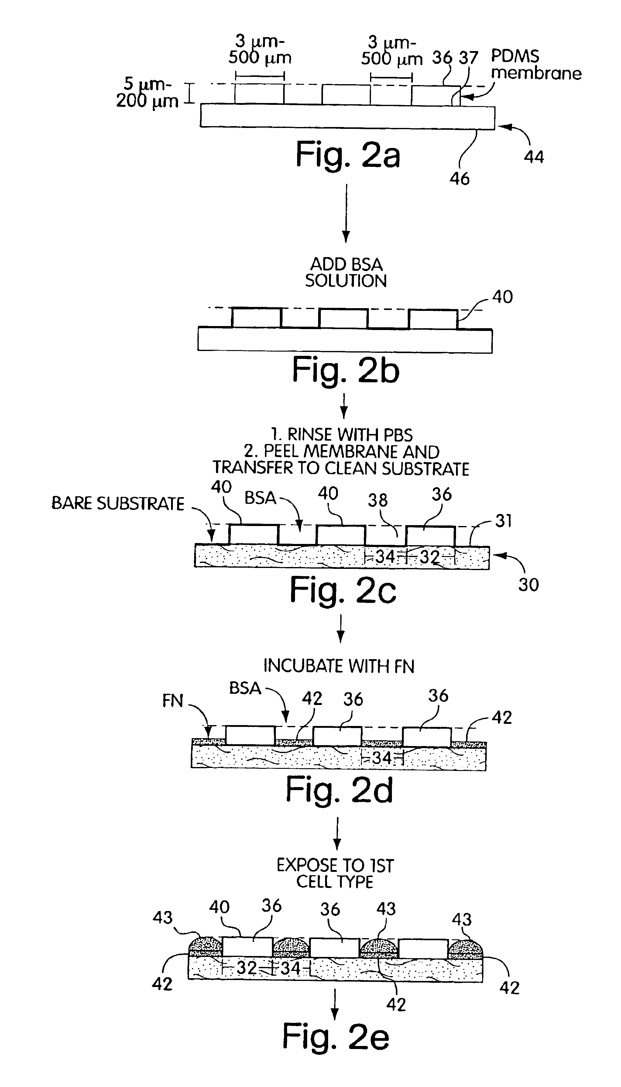
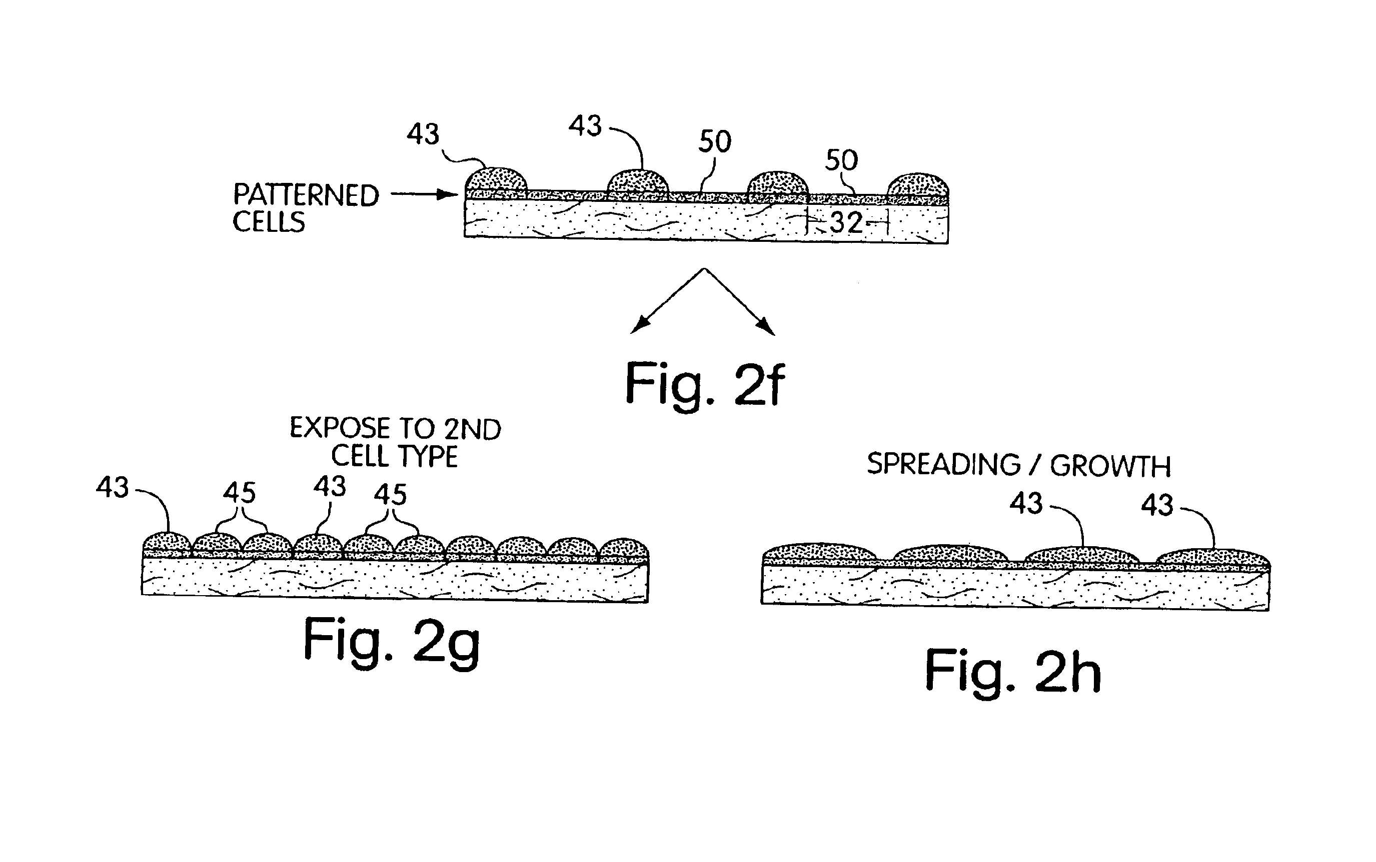
[0078]In a laminar flow hood, the membranes were placed on the surface of a sterile Petri dish with a few drops of ethanol. The liquid sterilized the membranes by killing bacteria. Drops of a buffered solution of BSA (1% w / v, in PBS or DMEM at pH=7.4) were placed on the membrane to cover the holes, in a manner schematically described in FIG. 2. Since the liquid did not fill the hydrophobic pores, vacuum was applied (˜30 sec) and released (˜500 mTorr) twice to extract the air trapped in the pores. BSA was allowed to adsorb to the surfaces for 15 min. The substrates were then rinsed three times with PBS; the membranes were peeled from the support in the presence of PBS, and transferred to a clean Petri dish covered with PBS to help seal the membrane onto the dish.

[0079]b) Patterning Proteins on Substrates.

[0080]Drops of a cell-adhesion promoter, buffered fibronectin (50 μg / mL, PBS with pH=7.4) or gela...

example 3

Cell Culture

[0083]a) Growth and Attachment.

[0084]Bovine adrenal capillary endothelial (BCE) cells were cultured under 10% CO2 on cell culture Petri dishes (Falcon) coated with gelatin in DMEM containing 10% calf serum, 2 mM glutamine, 100 μg / mL streptomycin, 100 μg / mL penicillin, and 1 ng / mL basic fibroblast growth factor (bFGF).2 Prior to incubation with the patterned substrates prepared using MEMPAT, cells were dissociated from culture plates with trypsin-EDTA and washed in DMEM containing 1% BSA (BSA / DMEM). The suspension of cells (typically 25,000 cells / mL, 2 mL total volume) was placed on the substrates in chemically defined medium (10 μg / mL high density lipoprotein, 5 μg / mL transferrin, 5 ng / mL basic fibroblast growth factor in 1% BSA / DMEM) and incubated in 10% CO2 at 37° C.

[0085]b) Fixing and Staining Cells.

[0086]Substrates that contained cells were fixed with PFA for 20 min and washed with PBS. The substrates were then washed with methanol for 1 min, and stained with Coomass...


PUM

PropertyMeasurementUnit
diameteraaaaaaaaaa
lengthaaaaaaaaaa
diameteraaaaaaaaaa

Abstract

The present invention provides a masking system for selectively applying cells to predetermined regions of a surface. A mask is positioned adjacent to a surface to cover some portions of the surface while allowing other portions of the surface to remain uncovered. Cells then are applied to uncovered portions of the surface and the mask removed. Alternatively, a cell-adhesion promoter is applied to uncovered portions of the surface, and then cells are applied to the surface before or after removal of the mask from the surface. The masking system can be pre-coated, at least on those surfaces which will come into contact with cells, with a cell-adhesion inhibitor to resist absorption of cells and thereby avoid cell damage when the mask is removed (if cells are deposited prior to removal of the mask). A polymeric elastomeric mask that comes into cohesive-conformal contact with a surface to be patterned can be used.

Description

RELATED APPLICATIONS[0001]This application claims priority to U.S. Provisional Patent Application Ser. No. 60 / 190,399, filed Mar. 17, 2000, entitled CELL PATTERNING VIA AN ELASTOMERIC MASK.[0002]This invention was sponsored by NSF Grant Nos. PHY-9312572, DMR-9809363, ECS-9729405 and AFOSR / SPAWAR Grant No. N66001-98-1-8915. The government has certain rights in the invention.FIELD OF INVENTION[0003]The present invention relates to methods for patterning cells on substrate surfaces via an elastomeric mask. These methods allow for the study of cell migration and growth.BACKGROUND OF THE INVENTION[0004]Cell adherence on substrate surfaces, particularly surfaces used for cell-culture such as glass or plastic, is necessary in many instances for the study of cells in furthering applications such as tissue engineering, biosensors, etc. Cell patterning, i.e. placing cells in discrete portions of a surface, has been provided by photolithography. Although the technology of photolithography is v...

Claims


Application Information

Patent Timeline
Patent Type & Authority Patents(United States)
IPC IPC(8): B01J19/00C12N11/06C12N11/00C12N1/00G01N33/48C40B60/14
CPCB01J19/0046C12M33/00B82Y5/00B82Y30/00C12N11/06C12M21/08C12M25/08B01J2219/00427B01J2219/0043B01J2219/00527B01J2219/00585B01J2219/00596B01J2219/00605B01J2219/00612B01J2219/00617B01J2219/00621B01J2219/00659B01J2219/00743C40B60/14B01J2219/00317C12M25/04
Inventor OSTUNI, EMANUELEKANE, RAVIWHITESIDES, GEORGE M.JACKMAN, REBECCA J.DUFFY, DAVID C.
Owner PRESIDENT & FELLOWS OF HARVARD COLLEGE
Learn More