
Vehicle-mounted power generator set

a power generator and vehicle-mounted technology, applied in the direction of electric control, speed sensing governors, instruments, etc., can solve the problems of generator through load resistance, electric power is wasted in load resistance, circuit elements that constitute the electric power conversion portion damaged,

Inactive Publication Date: 2006-05-18
KOKUSAN DENKI CO LTD
View PDF4 Cites 18 Cited by
  • Summary
  • Abstract
  • Description
  • Claims
  • Application Information

AI Technical Summary

Benefits of technology

[0010] An object of the present invention is to provide a vehicle-mounted power generator set that can prevent an overvoltage from being applied to an electric power conversion portion without reducing an engine output or fuel economy when a rotational speed of an engine increases while a vehicle is driving.

Problems solved by technology

The no-load induced voltage is applied to the electric power conversion portion, and may damage circuit elements that constitute the electric power conversion portion.
For the power generator set in Japanese Patent Application Laid-Open Publication No. 2004-104854, when the rotational speed of the engine increases while the vehicle is driving, the current passes from the generator through the load resistance and electric power is wasted in the load resistance.
This may increase the load of the engine when the engine rotates at a high speed, thereby reducing an engine output provided to drive wheels of the vehicle or reducing fuel economy.

Method used


Image

  • Vehicle-mounted power generator set
  • Vehicle-mounted power generator set
  • Vehicle-mounted power generator set

Examples


Embodiment Construction

[0033] Now, preferred embodiments of the present invention will be described with reference to the drawings.

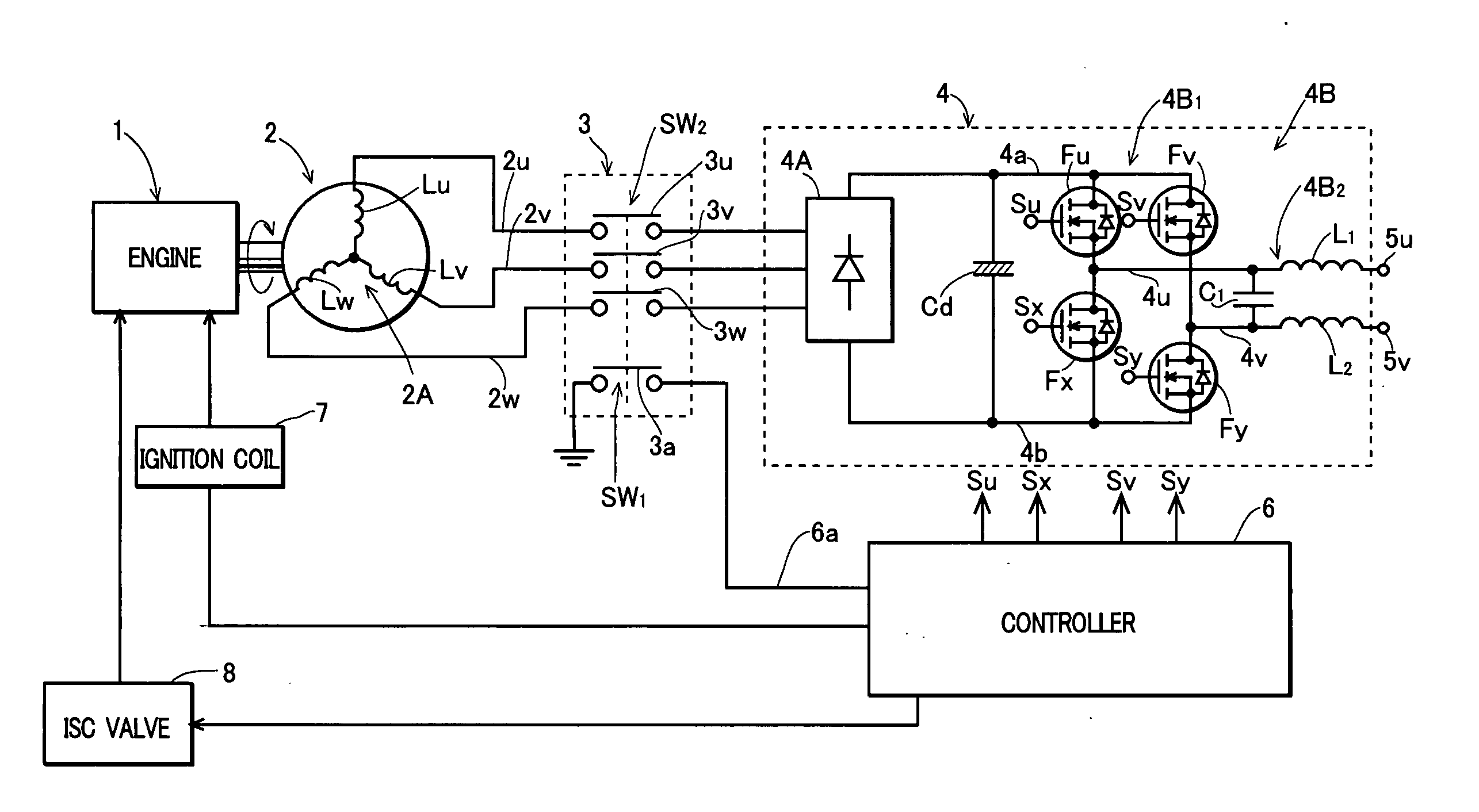
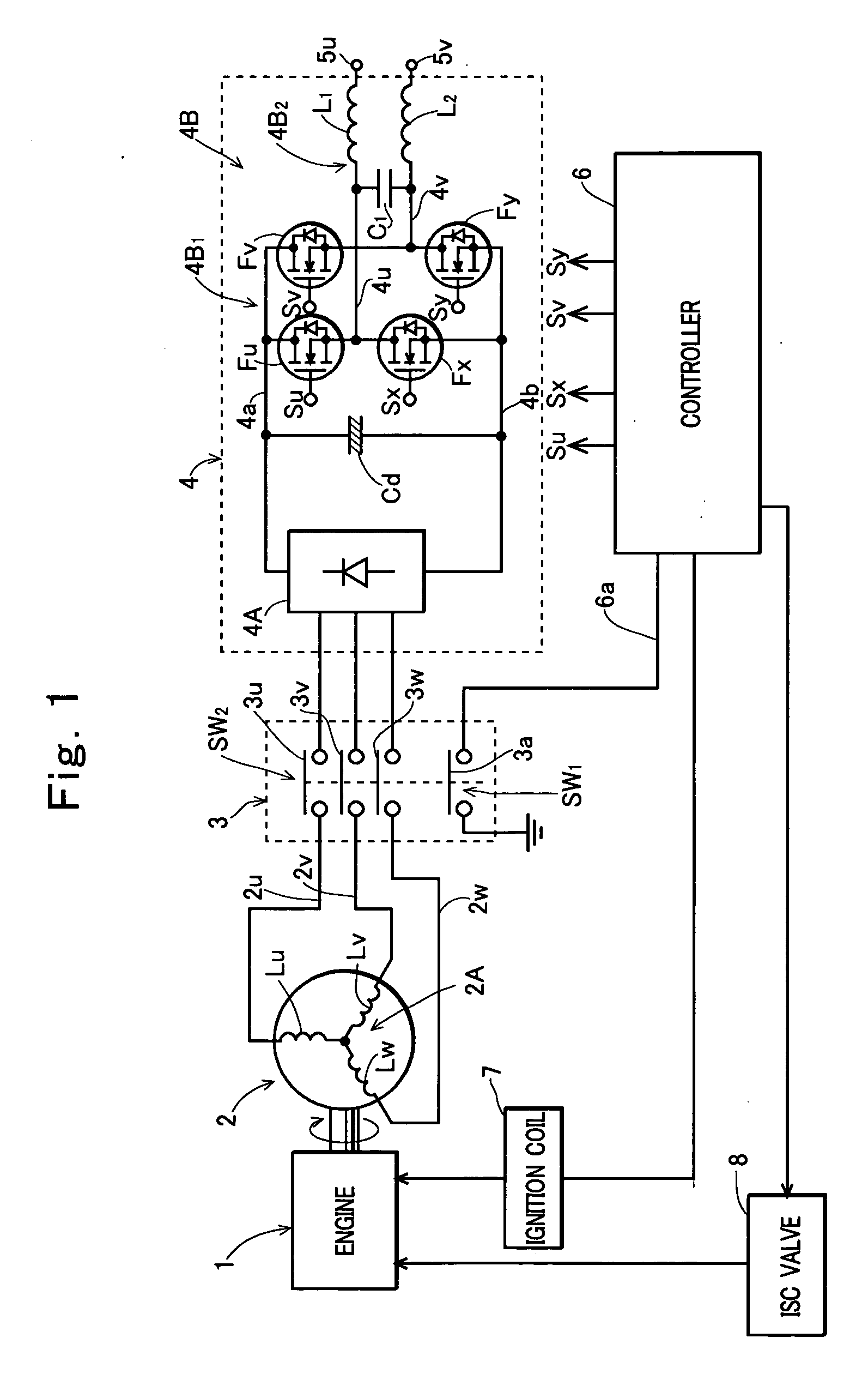
[0034]FIG. 1 is a circuit diagram of a construction of a first embodiment of the present invention. In FIG. 1, a reference numeral 1 denotes an engine for driving a vehicle, and 2 denotes a magnetic AC generator driven by the engine 1. The AC generator 2 has an armature winding (not shown) that supplies electric power to electrical components of the vehicle, and an armature winding 2A comprised of coils Lu to Lw three-phase star connected. Output terminals 2u to 2w of the generator 2 are drawn from ends opposite to a neutral point of the coils Lu to Lw, and a three-phase AC output obtained across the output terminals is input to an electric power conversion portion 4 via a switch 3.

[0035] In the shown example, the electric power conversion portion 4 is comprised of a converter 4A that converts an AC output of the AC generator 2 into a DC output, a smoothing capacitor Cd conn...


PUM


Abstract

A vehicle-mounted power generator set including: an AC generator driven by an engine of a vehicle; an electric power conversion portion that converts an output of the AC generator into an AC output having commercial frequency; a controller having electric power conversion portion control means for controlling the conversion portion to generate an AC output having commercial frequency when a control mode is a power generation mode, and engine control means for controlling the engine to rotate at a rotational speed suitable for supplying electric power from the conversion portion to a load when the control mode is the power generation mode and controlling the engine to be suitable for driving the vehicle when the control mode is the vehicle driving mode; and a control switch inserted between each output terminal of the AC generator and each input terminal of the electric power conversion portion, and controlled to be in an ON state when the control mode is the power generation mode and in an OFF state when the control mode is the vehicle driving mode.

Description

TECHNICAL FIELD OF THE INVENTION [0001] The present invention relates to a power generator set mounted in a vehicle. BACKGROUND OF THE INVENTION [0002] As disclosed in Japanese Patent Application Laid-Open Publication No. 2004-92634, engine driven vehicles such as ATVs (All Terrain Vehicles, so-called buggies), tractors, or recreation vehicles that are vehicles intended mainly for driving on rough ground have been incorporating a power generator set driven by an engine for driving a vehicle to supply commercial AC electric power of AC 100 V or AC 200 V (50 Hz or 60 Hz), or the like to an external electrical load such as an electric tool or a home appliance while the vehicle is stopped, in order to allow the external electrical load to be used outdoors. [0003] As known, a vehicle-mounted power generator set is comprised of an AC generator driven by an engine and an electric power conversion portion that converts an output voltage of the AC generator into an AC voltage having a fixed ...

Claims


Application Information

Patent Timeline
Patent Type & Authority Applications(United States)
IPC IPC(8): B60L1/00H02H7/06
CPCF02D31/001F02D41/0205F02D41/083
Inventor KISHIBATA, KAZUYOSHIENDOU, MASAHIKOSEKITA, TOMOAKI
Owner KOKUSAN DENKI CO LTD
Learn More