
Self-repairing ceramic coatings

a ceramic coating and self-repairing technology, applied in the direction of prosthesis, instruments, ligaments, etc., can solve the problems of thrombosis and embolism formation, limiting factors, mechanical failure of implants,

Inactive Publication Date: 2005-03-22
AITA CAROLYN
View PDF21 Cites 103 Cited by
  • Summary
  • Abstract
  • Description
  • Claims
  • Application Information

AI Technical Summary

Benefits of technology

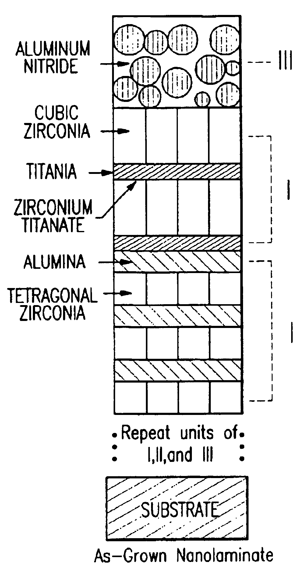
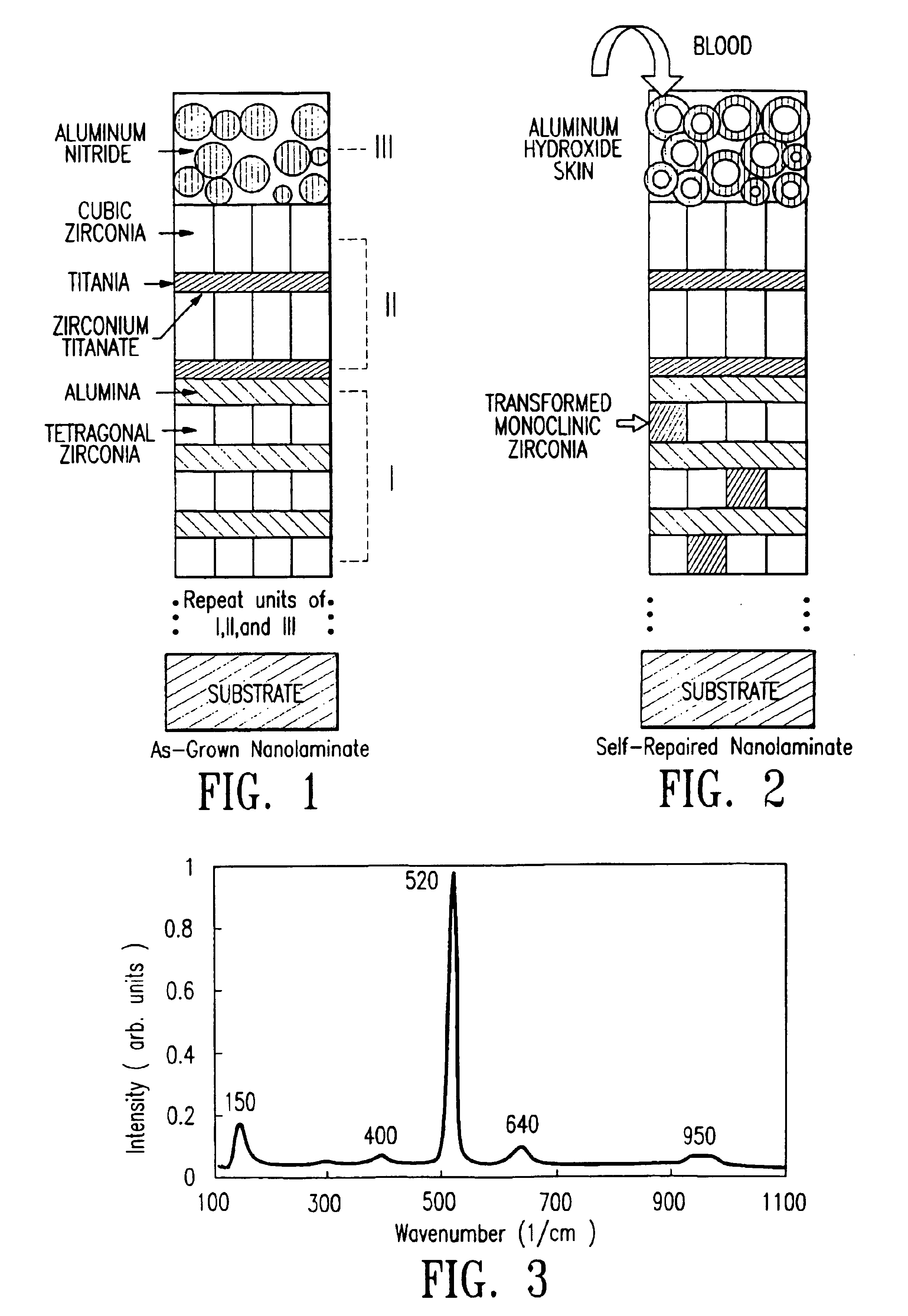
The present invention is directed to a multilayered protective coating formed of ceramic materials. The coating comprising an inner component or module which has at least one, preferably two layers of ceramic materials such as zirconia, titania and alumina therein. The coating further comprises an outer component or module disposed on the inner component formed of a water swellable ceramic material capable of forming a hydrate or hydroxide compound upon contact with an oxygen containing environment, e.g. water based fluids such as blood. Preferably, ceramic material...

Problems solved by technology

A key problem in interfacing a biomaterial with blood revolves around the characteristics of the implant surface.
Thrombus and embolism formation at the blood-implant interface is of foremost concern, and is the technology limiting factor in implant design and materials selection.
The surface reactivity of the metallic implants at the blood-implant interface leads to bulk electrochemical corrosion and localized stress corrosion, which in turn, leads to mechanical failure of the implant and ion contamination of the blood.
However, the use of polymers poses a major problem, namely, chemical degradation over time resulting in thrombus and embolism formation as well as the production of harmful wear-related debris.
However, ceramic implants exhibit the same major drawback as that for all traditional bulk ceramic structures in their inability to deform plastically under either or both static and cyclic loading.
The lack of flexibility of the bulk ceramics leads to difficulty in manufacturing implants and microcracking during the implant's lifetime in the body due to fatigue failure.

Method used


Image

  • Self-repairing ceramic coatings
  • Self-repairing ceramic coatings

Examples


example i

Transformation-Toughening Zirconia-Alumina Coatings

Nanolaminates consisting of polycrystalline zirconia and vitreous alumina bilayer stacks were grown at room temperature by reactive sputter deposition. The formation of tetragonal zirconia in the as-grown material was consistent with a finite crystallite size effect. Solely the tetragonal phase was produced in zirconia layers whose thickness was less than a critical value, e.g., less than 6 nm for room temperature growth. With respect to in-service transformation-toughening, high resolution transmission electron microscopy (HREM) was used to study the post-deposition, stress-induced tetragonal to monoclinic zirconia transformation, and its plane and direction invariants were identified.

The transformation was localized to nano-sized regions within individual zirconia layers, constrained by the alumina. The macroscopic effect of the toughness resulting from this transformation was confirmed by scanning electron microscopy of a cross-s...

example ii

Cubic Zirconia and Zirconia Titanate Formation Zirconia-Titania Nanolaminates at Room Temperature

As the thickness of each constituent layer in a nanolaminate decreases, the interface between layers plays an increasingly important role in determining the overall properties of the coating. In turn, chemical reactivity between constituents plays an important role in determining the properties of the interface, even at low growth temperature. To illustrate this point, two pseudobinary oxide systems that represented extremes in chemical reactivity between constituents were compared, namely, zirconia-alumina and zirconia-yttria. The pseudobinary equilibrium phase diagram of zirconia and alumina showed very limited mutual solid solubility and no compounds. On the other hand, the pseudobinary phase diagram of zirconia and yttria showed a series of solid solutions (alloys) covering the entire composition range from pure zirconia to pure yttria, as well as compounds. These two model systems a...

example iii

Nanocrystalline Aluminum Nitride for Self-Sealing Corrosion Protection of Steel

Traditionally, ceramic coatings are used to protect an underlying material from corrosion by providing an inert, non-porous barrier to diffusion. In that case, any defect in the coating, such as a microscopic pore or pinhole, is a possible source of failure due to pitting corrosion. In addition, polycrystalline coatings with a typical columnar crystal structure are intrinsically vulnerable, because this microstructure provides fast diffusion paths to the substrate. To remedy the intrinsic problem of a columnar microstructure, multilayer coatings may be used to interrupt crystallite growth. However, pitting corrosion due to microscopic defects is still a concern.

The present inventors identified another, active, type of corrosion protection by ceramic coatings, referred to here as “self-sealing” behavior. To develop the self-sealing ceramic coating aluminum nitride coating on steel, as the prototype materia...


PUM

PropertyMeasurementUnit
Thicknessaaaaaaaaaa
Thicknessaaaaaaaaaa
Thicknessaaaaaaaaaa

Abstract

A protective coating for a substrate is disclosed having an outer component or module formed of a swellable material and an inner module formed of a plurality of layer or bilayers formed of ceramic material. The coating comprising a plurality of modules comprising a first module comprising a number (m) of bilayers comprising zirconia and alumina wherein (m) is a number greater than 1. The coating further comprises a second module disposed on the first module comprising a number (n) of bilayers comprising zirconia and titania wherein (n) is a number greater than 1. The coating further comprises a third module disposed on the second module comprising a third-module compound capable of forming a hydrate or hydroxide compound upon contact with an oxygen containing environment.

Description

FIELD OF INVENTIONThe present invention relates to coatings for devices and implements and the like suitable for intracorporeal applications, particularly coatings for intravascular applications.BACKGROUND OF THE INVENTIONBiomaterials are synthetic materials used to replace or augment a part of a living system or to function in contact with living tissue. Among the many causes for mortality among human beings, cardiovascular diseases account for a major portion of such deaths. Therefore, continuous improvements in the development of new and improved biomaterials capable of replacing parts of the cardiovascular system is extremely important. The primary requirements for biomaterials for long-term implants, e.g. heart valve prostheses, stents, and vascular grafts, are biocompatibility, thrombresistivity, nontoxicity, and durability. Furthermore, biomaterials should be nonirritating to tissue and nondegradable in the harsh physiological environment, neither absorbing blood constituents...

Claims


Application Information

Patent Timeline
IPC IPC(8): A61L27/50A61L27/00A61L27/30A61L31/08A61L31/14
CPCA61L27/306A61L27/50A61L31/14A61L31/088Y10T428/265A61L2400/12
Inventor AITA, CAROLYN R.YAKOVLEV, VLADISLAV V.CAYTON, MARY M.MIRHOSEINI, MAHMOODAITA, MICHAEL
Owner AITA CAROLYN
Learn More