
Soft transition converter

a converter and soft transition technology, applied in the direction of ac-dc conversion, ac-dc conversion, efficient power electronics conversion, etc., can solve the problems of increasing the level of electromagnetic interference (emi), increasing the switching loss, and reducing the efficiency of high frequency operation, so as to and reduce the loss of reverse recovery

Inactive Publication Date: 2005-03-01
DELTA ENERGY SYST SWITZERLAND
View PDF18 Cites 58 Cited by
  • Summary
  • Abstract
  • Description
  • Claims
  • Application Information

AI Technical Summary

Benefits of technology

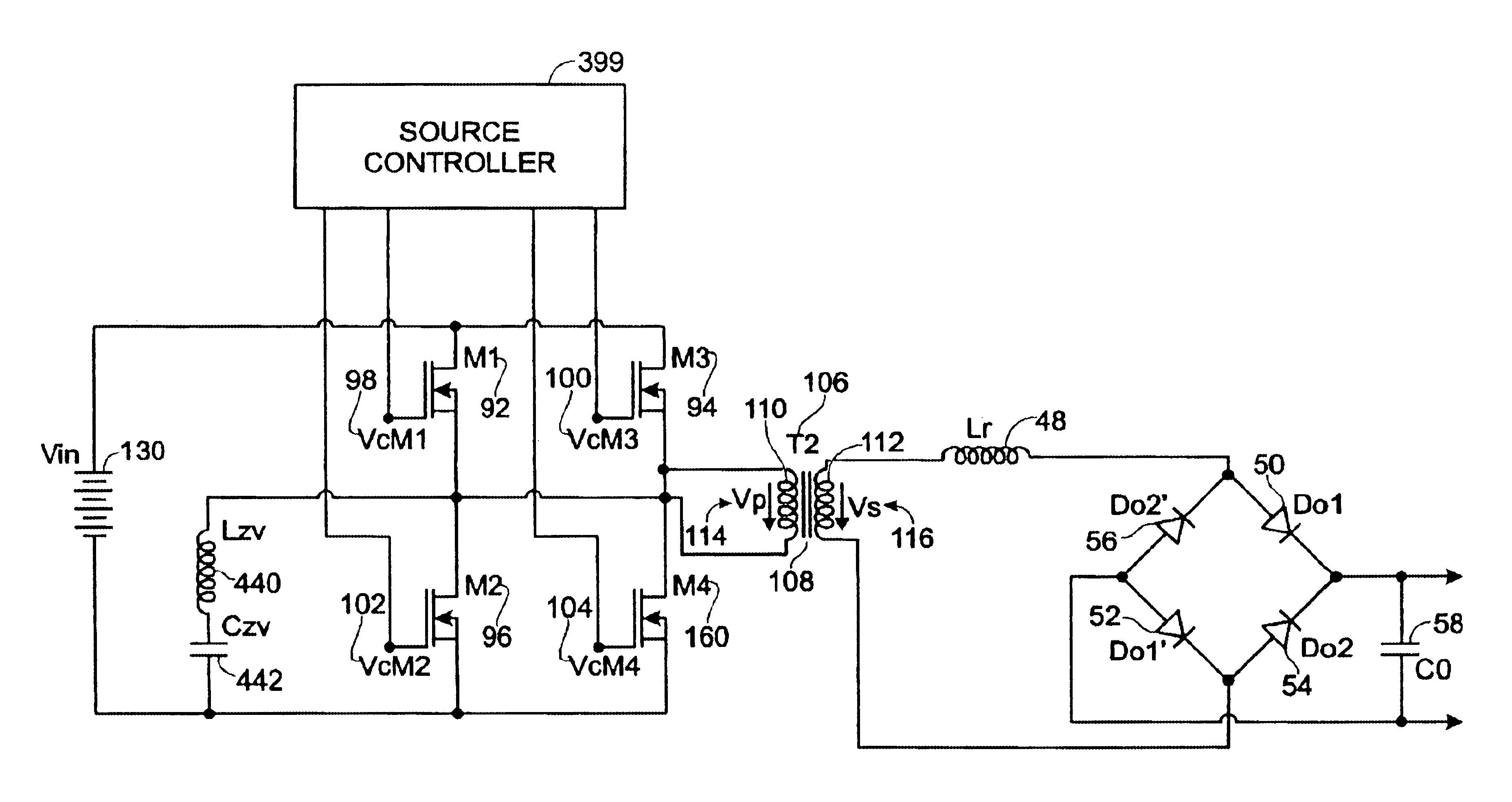
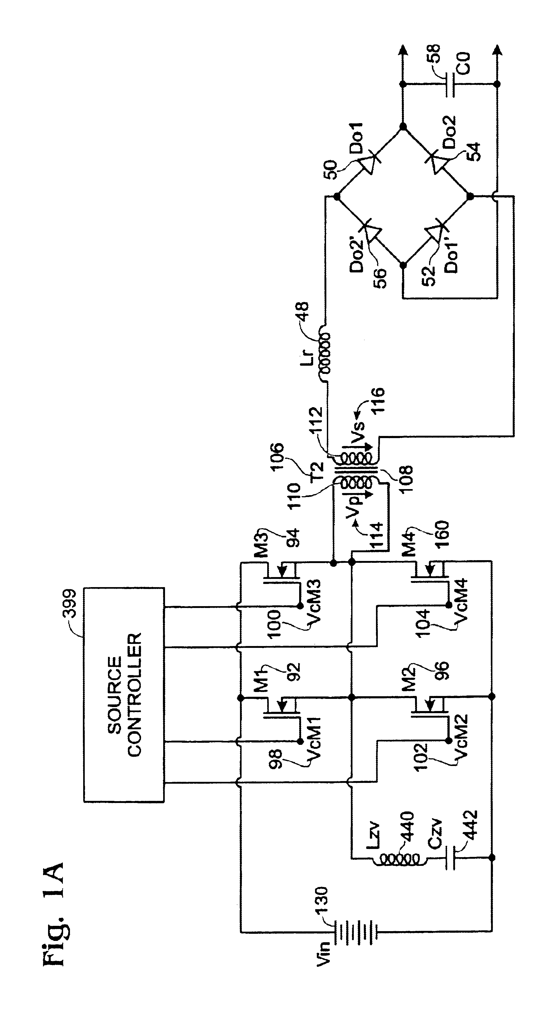
Another major advantage of this topology is the fact that the current slope through the rectifier at turn off is controlled by the soft commutation inductor. As a result there is a controlled dI / dt. A soft current through the rectifier at turn OFF reduces considerably the reverse recovery current. The clamped voltage across the output rectifiers in association with the soft current slope at turn OFF leads to reduced reverse recovery losses. If the circuits operate in continuous mode the reverse recovery losses are reduced, and if we operate in discontinuous conduction mode the reverse recovery losses are actually eliminate. This is due to the fact that the current through the rectifiers reaches zero prior the reverse voltage is applied to them.

Problems solved by technology

Using prior art topologies such as forward or flyback, which employ “hard” switching techniques makes high frequency operation less efficient.
An increase in switching frequency leads to an increase in switching losses and an increase in the level of electromagnetic interference (EMI).
Another power loss mechanism is due to the reverse recovery in the output rectifiers.
During the period of time when there is a negative voltage across the diode and negative current is flowing through it, there will be power dissipation in the device.
The reverse recovery characteristics are getting worse for higher voltage rectifiers.
As a result the reverse recovery loss becomes a significant loss mechanism for higher output voltage applications.
The reverse voltage across the rectifier can reach very high levels and can exceed the voltage break down of the device, leading to failure.
This leads to complex circuits and which negatively affects the efficiency and the reliability.

Method used


Image

  • Soft transition converter
  • Soft transition converter
  • Soft transition converter

Examples


Embodiment Construction

For the AC-DC and DC-DC converters for high voltage application wherein the use of Schottky rectifiers is not possible due to high voltage across the rectifiers, one of the major obstacles is the reverse recovery loss of the rectifiers. The reverse recovery losses are proportional with the current slope through rectifier at turn OFF, the reverse voltage across the rectifier after the rectifier exhibits high impedance, the temperature, frequency of operation and the device characteristics. Additional snubber circuits are often used to reduce the voltage stress on the rectifiers during switching. The frequency of operation has to be also reduced which leads to poor volumetric efficiency of the converters. In FIG. 2 are presented a prior art an AC-DC converter. An AC source drives the primary of the transformer T6, 950. There is inherent leakage inductance in the transformer, which acts as a current source during commutation of the rectifiers 406 and 408. In the right side of the recti...


PUM


Abstract

The present invention is a circuit and method for reducing switching and reverse recovery losses in the output rectifiers while creating zero voltage switching conditions for the primary switchers. There are described two output configurations, one employing a soft commutation inductor element a bridge rectifier and a output filter capacitor, the second using a soft commutation inductor element a rectification-filtering bridge composed by two capacitors and two capacitors. Both secondary circuits can be driven by three primary circuits. A first circuit is a full bridge with phase shift control, and a second circuit is a half bridge topology with an additional bydirectional switch which achieves two goals, on to get soft switching commutation across all the primary switches, the second to create the right waveforms in the secondary suitable with the claims in this invention. The third topology is a phase shifted two transistors forward. The circuits claimed in this invention can provide soft commutation across the primary switching elements and secondary rectifier means, clamping the voltage across the rectifiers to the output voltage eliminating the need for snubbers circuits both in primary and the secondary section.

Description

BACKGROUND OF INVENTION1. Field of the InventionThis invention relates to DC-to-DC converters, DC-to-AC inverters and AC-to-DC converters. The major characteristic of this power conversion technique is that primary switching elements switches at zero voltage and the secondary rectifiers means have negligible reverse recovery losses.2. Description of the Prior ArtThere is a continuing industry demand for increasing power density, which means more power transferred in a given volume. A method for increasing the power transfer through the converter is to increase the switching frequency in order to minimize the size of magnetic and the capacitors. Using prior art topologies such as forward or flyback, which employ “hard” switching techniques makes high frequency operation less efficient. The switching losses associated with switching elements, which turn on when there is a voltage across them, are proportional with the switching frequency. An increase in switching frequency leads to an...

Claims


Application Information

Patent Timeline
IPC IPC(8): H02M3/337H02M3/24
CPCH02M3/3376H02M1/0058H02M1/0085Y02B70/10
Inventor JITARU, IONEL
Owner DELTA ENERGY SYST SWITZERLAND
Learn More