
Magnetic recording medium including aluminum layer having holes and production method thereof

a technology of aluminum layer and recording medium, which is applied in the direction of magnetic bodies, soldering apparatuses, instruments, etc., can solve the problems of limited structure control, easy bringing a superparamagnetic effect, and noise accompanying the domain wall

Inactive Publication Date: 2005-02-22
CANON KK
View PDF20 Cites 39 Cited by
  • Summary
  • Abstract
  • Description
  • Claims
  • Application Information

AI Technical Summary

Benefits of technology

The solution achieves improved record and reproduction characteristics with low noise and high signal-to-noise ratios, allowing for high-density recording and stable magnetization due to uniform c-axis orientation and reduced magnetization inversion.

Problems solved by technology

Therefore, a volume of a magnetic particle becomes extremely small, resulting in the tendency of easily bringing a superparamagnetic effect.
Although effects of increasing a recording magnetic field and enhancing record and reproduction are expected in this two-layer type of medium having the backing layer, it is also pointed out that there is a problem that a reversal of magnetization of the soft magnetic layer, and noise accompanying domain wall transfer, etc. are caused.
However, since each thin insulating layer remains by this method, alternating current electrodeposition with nearly 10 to 50 V of high voltage becomes necessary for the electrodeposition into nanoholes.
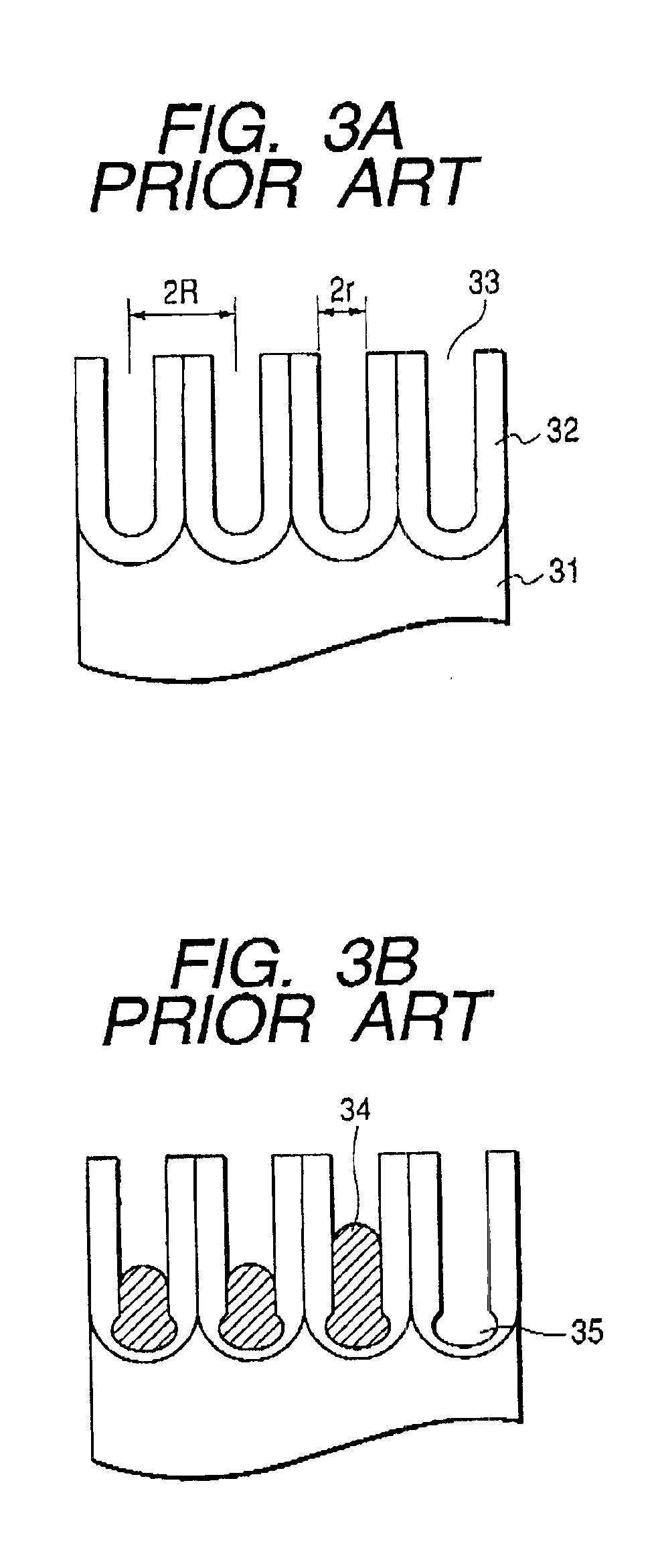
Since there is limitation in structure control of electrodeposition inclusion objects in the electrodeposition with such a high voltage, polycrystals are usually electrodeposited unevenly.
Of course, the dispersion in orientations of crystallographic axes of the microcrystals is also a cause of the deterioration of the characteristics.
In addition, it is difficult to fill the pores with the above-described alumite magnetic substance, and it is not possible to control the crystal orientation of magnetic substances, and in particular, to control c-axis orientation.
Furthermore, it is insufficient to control an amount of electrodeposition inside each pore.

Method used


Image

  • Magnetic recording medium including aluminum layer having holes and production method thereof
  • Magnetic recording medium including aluminum layer having holes and production method thereof
  • Magnetic recording medium including aluminum layer having holes and production method thereof

Examples


example 1

[0058]This example relates to a manufacturing method and respective shapes and orientation of a hard magnetic substance filling anodic oxidized alumina nanoholes.

[0059]A substrate on which a Ti film of 10 nm thick and a Cu film of 20 nm thick, and an aluminum film of 500 nm thick had been formed on Si substrate by sputtering was anodized by applying 40 V in 0.3 M of oxalic acid aqueous solution at 16° C. Next, the substrate was immersed for 25 minutes in 0.5 wt % of phosphoric acid aqueous solution for expanding hole diameters. At this time, the (111) face of the Cu film was oriented in the direction perpendicular to the substrate, and since a Cu face was exposed in each nanohole bottom, the Cu film had good conductivity.

[0060]The anodic oxidized alumina nanoholes thus produced was filled with Co, which is a hard magnetic substance. Here, an aqueous solution that consists of cobalt sulfate (II) heptahydrate of 0.2 M and boric acid of 0.3 M was used at 24° C. for the electrodepositio...

example 2

[0066]This example relates to the formation of an alloy of Co and Cu by mixing the electrodeposition liquid in Example 1 and a copper sulfate (II) aqueous solution.

[0067]First, similarly to Example 1, the alumina nanoholes were prepared.

[0068]An aqueous solution that a copper sulfate (II) pentahydrate of 0.01 M was mixed with an aqueous solution, which consists of cobalt sulfate (II) heptahydrate of 0.2 M and boric acid of 0.3 M, in a 1:1 ratio was used at 24° C. for the electrodeposition.

[0069]The electrodeposition was performed with applying −1.0 V to the Ag / AgCl reference electrode.

[0070]Then, electrodepositions overflowed on the surface were removed by polishing, and X-ray diffractometry and magnetization measurement were performed.

[0071]As the result of X-ray diffraction, it was verified that the c-axes of electrodepositions are oriented dominantly.

[0072]Furthermore, although the saturation magnetization of this ample decreased to 680 (emu / cc) than the case of only Co according...

example 3

[0074]This example relates to a manufacturing method and orientation of a nonmagnetic substance and soft magnetic substance portions in the structure of fillers, and the orientation of a hard magnetic substance portion caused by the result.

[0075]First, possible structure of the fillers, as shown in FIGS. 4A to 4E, is not only a hard magnetic substance only in Example 1 (FIG. 4A), but also a hard magnetic substance / a nonmagnetic substance (FIG. 4B), a hard magnetic substance / a soft magnetic substance (FIG. 4C), a hard magnetic substance / a nonmagnetic substance / a soft magnetic substance (FIG. 4D), or a hard magnetic substance / a soft magnetic substance / a nonmagnetic substance (FIG. 4E). Referring to FIGS. 4A to 4E, the hard magnetic substance is indicated by 41, the base electrode layer by 42, the substrate by 43, the nonmagnetic substance portion by 44, and the soft magnetic substance portion by 45.

[0076]First, as shown in Example 1, the alumina nanoholes were prepared, and the electr...


PUM

PropertyMeasurementUnit
diameteraaaaaaaaaa
deposition velocityaaaaaaaaaa
voltageaaaaaaaaaa

Abstract

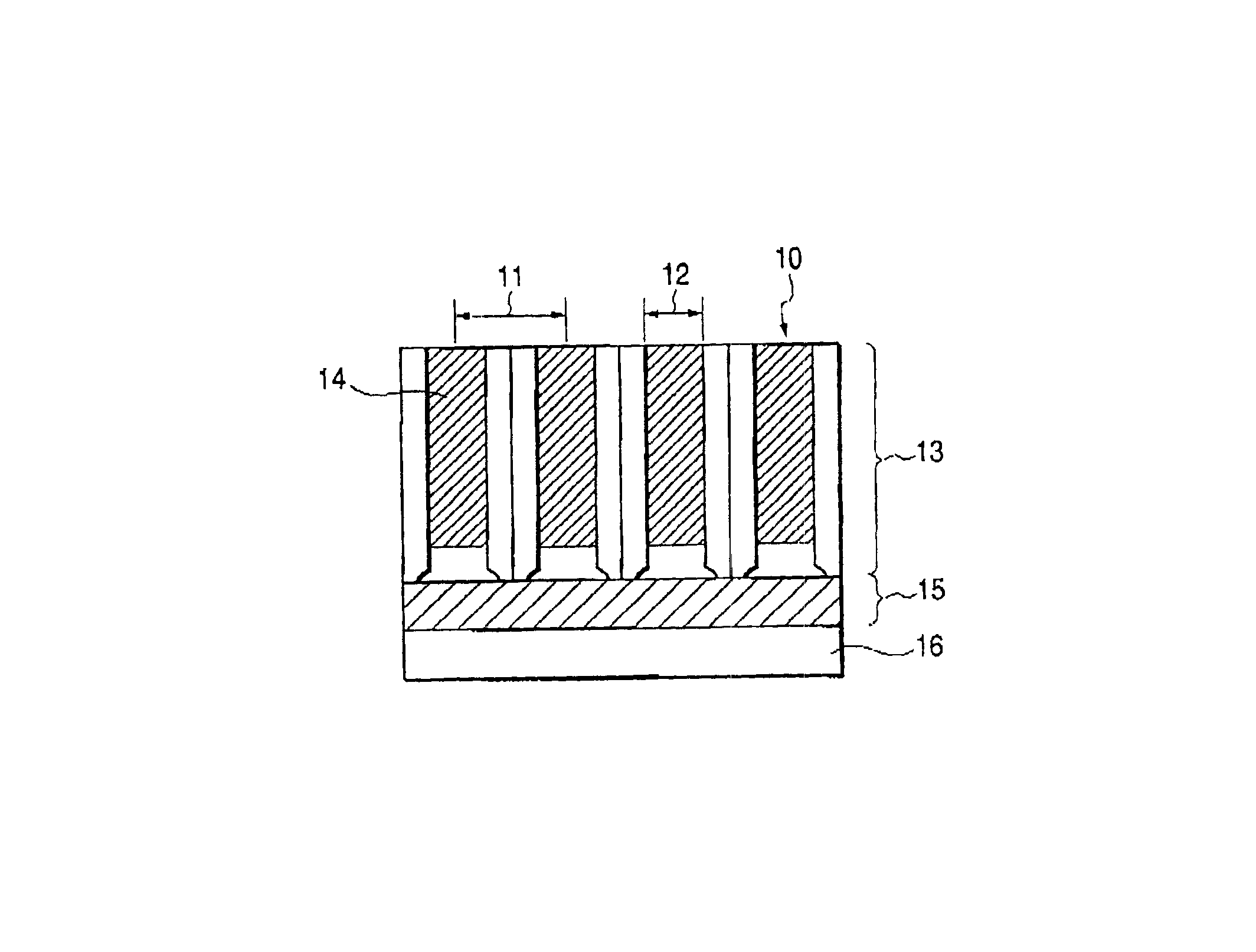
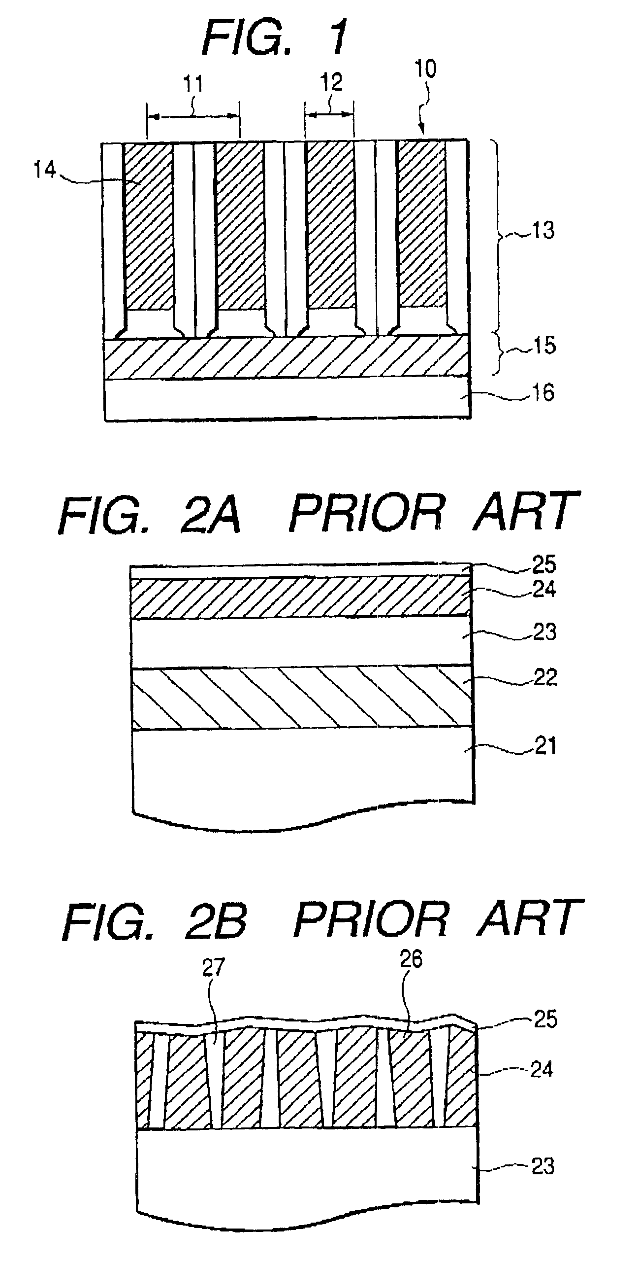
To provide a magnetic recording medium with good record and reproduction characteristics. In the magnetic recording medium having an anodic oxidized alumina nanohole film filled with a magnetic substance, the anodic oxidized alumina nanohole film 13 is formed on a substrate 16 with at least one base electrode layer 15 sandwiched therebetween, the base electrode layer 15 is a film that has fcc structure and whose (111) face is oriented in the direction perpendicularly to a substrate, and the fillers 14 in the alumina nanoholes 10 have hcp structure and include hard magnetic substance whose principal component is Co and whose c-axis is perpendicular to the substrate.

Description

BACKGROUND OF THE INVENTION[0002]1. Field of the Invention[0003]The present invention relates to a magnetic recording medium and a production method thereof, and in particular, to a perpendicular magnetic recording medium, where reproduction noise is low and high density recording is possible, and a production method thereof.[0004]2. Related Background Art[0005]Increase in information recording capacity of magnetic disk units and the like is desired with sharp increase of information processing in recent years. In particular in hard disk drives, an information-recording amount per unit area is now increasing with an annual rate of 60% or more. The information-recording amount is desired to continue to increase, and miniaturization and a higher density are also desired for use as a portable recording device and the like.[0006]In a magnetic recording medium for a hard disk drive used conventionally, a longitudinal magnetic recording method is adopted, and magnetization is recorded in ...

Claims


Application Information

Patent Timeline
Patent Type & Authority Patents(United States)
IPC IPC(8): G11B5/855G11B5/858G11B5/64G11B5/65G11B5/738G11B5/667G11B5/84
CPCG11B5/855G11B5/858Y10T428/12667Y10T428/1291Y10T428/25Y10T428/1275Y10T428/256Y10T428/325Y10T428/31Y10T428/24479Y10T428/12465
Inventor YASUI, NOBUHIRODEN, TOHRU
Owner CANON KK
Learn More