
Dynamic plasmonics-enabled signal enhancement, a device comprising the same, and a method using the same

Inactive Publication Date: 2008-11-20
MORPHO DETECTION INC
View PDF13 Cites 17 Cited by
  • Summary
  • Abstract
  • Description
  • Claims
  • Application Information

AI Technical Summary

Problems solved by technology

The sensitivity of instruments containing the lamp source is therefore not always satisfactory.
Laser diodes are however, expensive to produce and are not tunable.
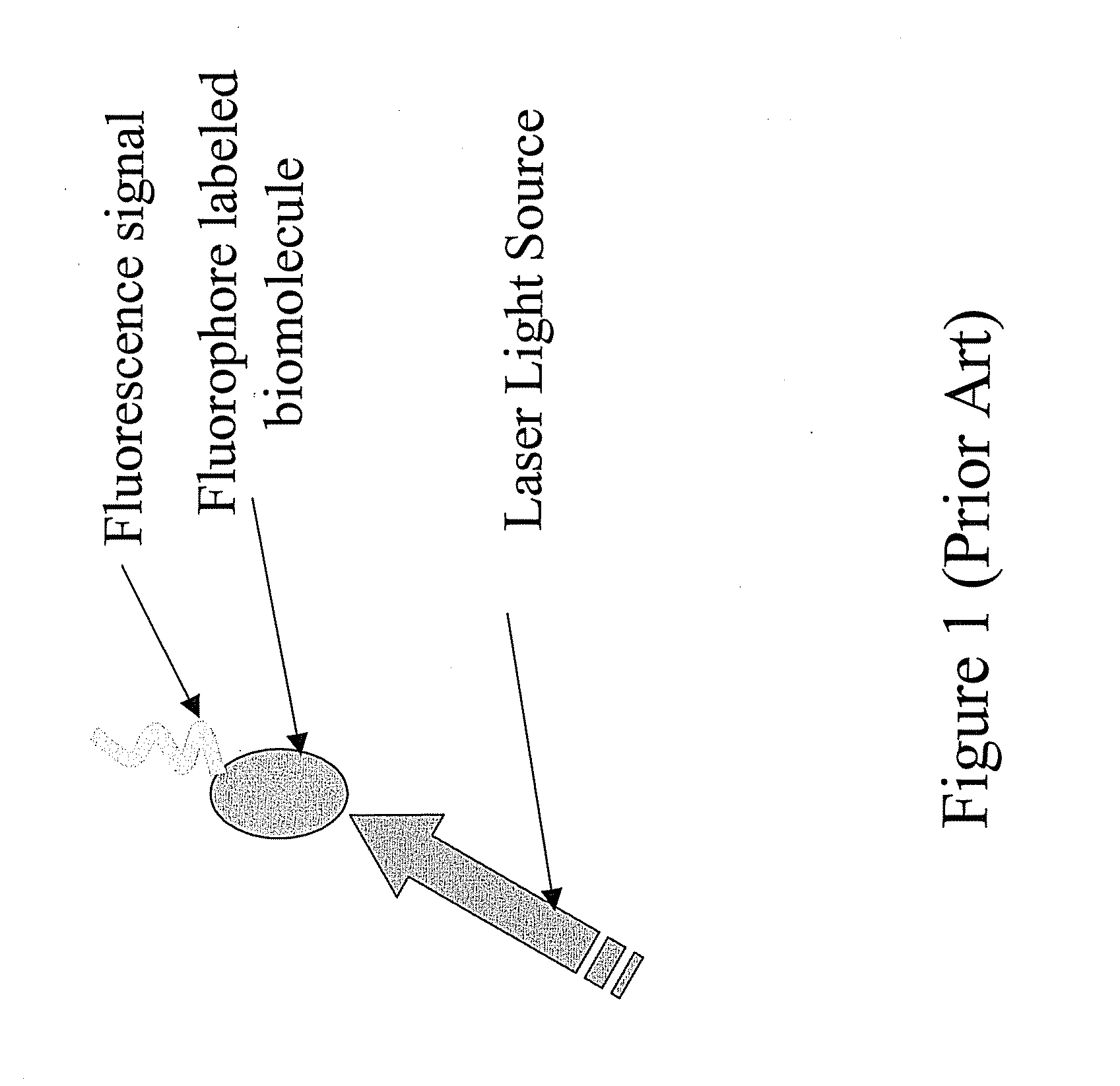
Having a collection of lasers to probe multiple species of biomolecules with different fluorescent fluorophores is therefore practically difficult. FIG. 1 depicts a conventional fluorescence-based technique using a laser to perform molecular imaging and diagnostics.
However, the fluorescence signal emitted by the molecule can be weak depending upon the light source used for the irradiation.
Poorly performing substrates have plagued surface enhanced Raman spectroscopy (SERS) as an analytical technique since its discovery in 1977 and have effectively limited its acceptance as a reliable method for chemical analysis.
Despite the discovery of single molecule sensitivity for SERS in 1997 and the subsequent explosion of interest in SERS, little progress has been made toward the development of useful substrates suitable for commercial manufacturing.
Raman scattering is an extremely inefficient process where only one in 108 incident photons is Raman scattered.
Historically, a number of challenges have existed that have inhibited the successful development and commercialization of SERS substrates.
Fabrication methods are complex multi-step laboratory processes that are not suitable for scale up to production manufacturing levels.
Finally, substrate morphology on the nanoscale is difficult to reproduce and the relationship between substrate nanoscale morphology and SERS enhancement factors is poorly understood.

Method used


Image

  • Dynamic plasmonics-enabled signal enhancement, a device comprising the same, and a method using the same
  • Dynamic plasmonics-enabled signal enhancement, a device comprising the same, and a method using the same
  • Dynamic plasmonics-enabled signal enhancement, a device comprising the same, and a method using the same

Examples


Embodiment Construction

[0022]The use of the terms “a” and “an” and “the” and similar references in the context of describing the invention (especially in the context of the following claims) are to be construed to cover both the singular and the plural, unless otherwise indicated herein or clearly contradicted by context. The modifier “about ” used in connection with a quantity is inclusive of the stated value and has the meaning dictated by the context (e.g., it includes the degree of error associated with measurement of the particular quantity). All ranges disclosed herein are inclusive of the endpoints, and the endpoints are independently combinable with each other.

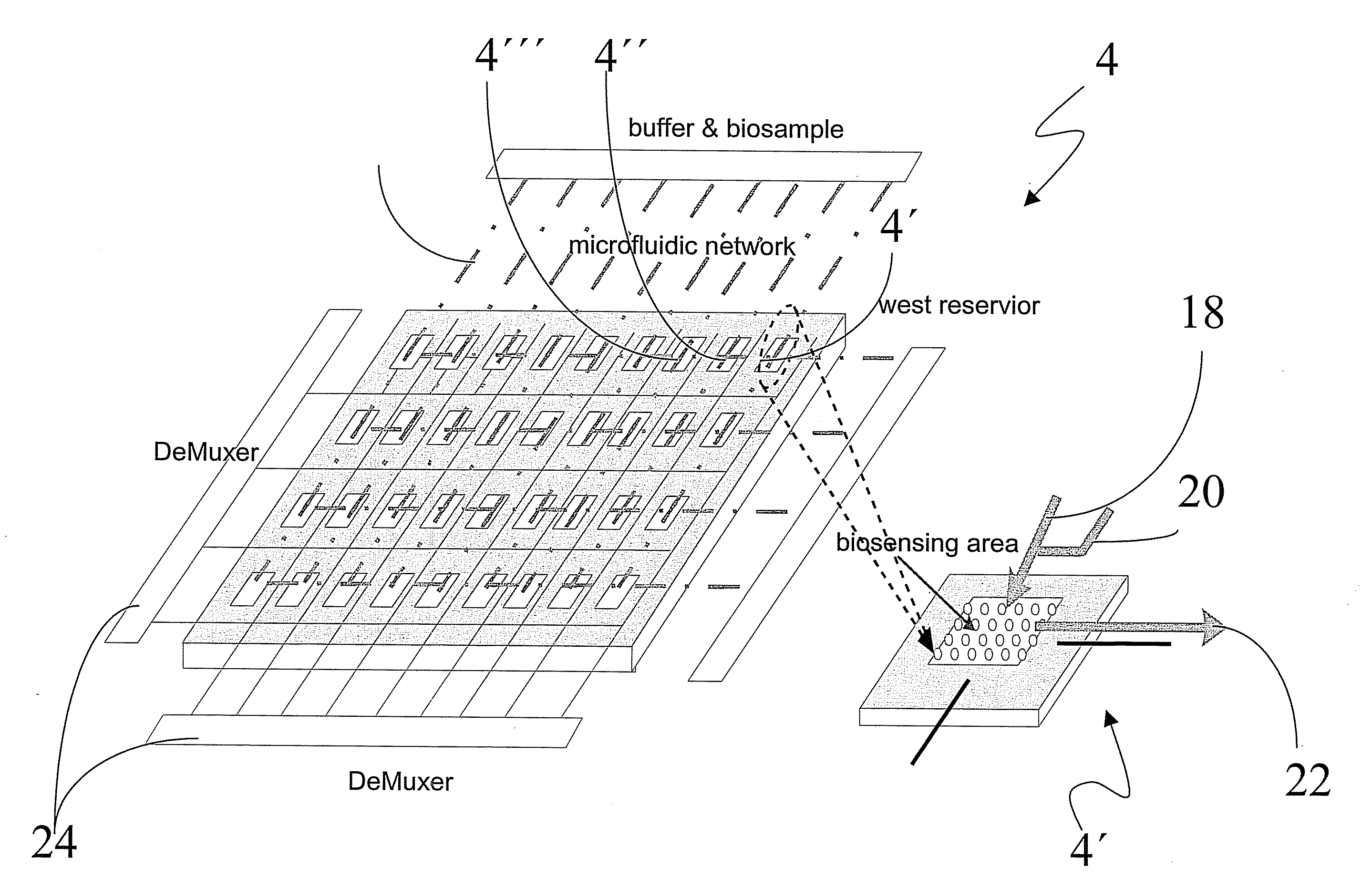
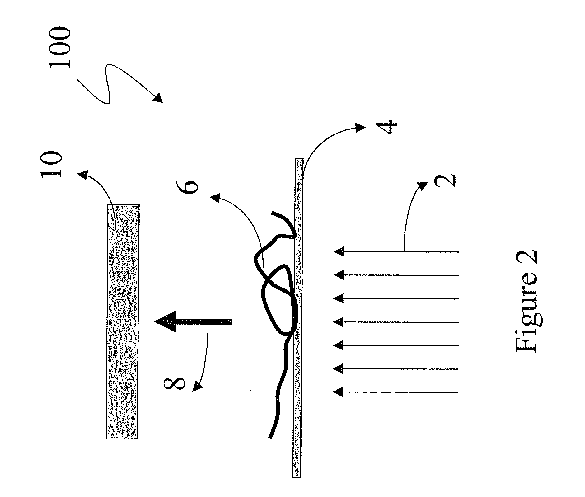
[0023]Disclosed herein is a device that comprises a source of light and a tunable plasmonics platform for the detection, diagnosis and / or imaging of an unknown specimen that is disposed upon the plasmonics platform. The device further comprises a microelectromechanical system (MEMS) and / or a nanoelectromechanical system (NEMS) that enables t...


PUM


Abstract

Disclosed herein is a plasmonics platform comprising a substrate; a plurality of periodically spaced nanoholes and / or nanoparticles disposed upon the substrate; wherein the average first order of periodicity between the nanoholes and / or the nanoparticles is about 5 to about 1,000 nm; and a microelectromechanical and / or a nanoelectromechanical system in operative communication with the substrate so as to vary the average first order of periodicity between the nanoholes and / or the nanoparticles.

Description

BACKGROUND OF THE INVENTION[0001]This disclosure relates to dynamic plasmonics-enabled signal enhancement, devices comprising the same, and methods using the same.[0002]Fluorescence-based and surface enhanced Raman spectroscopy (SERS) are beginning to be widely used in molecular imaging and diagnostics. Techniques using fluorescence include fluorescence lifetime imaging (FLIM), where the imaging of fluorescence lifetime provides a robust means of acquiring spatially resolved information regarding the local environment of a distributed fluorophore in biological tissue and other heterogeneous or turbid media. Other techniques that use picosecond time resolution and nanometer spectral resolution are Foerster's Resonance Energy Transfer (FRET), Fluorescence Activated Cell Sorting (FACS), Fluorescence Lifetime Micro-Spectroscopy (FLMS), polarized fluorescence recovery or redistribution after photobleaching (PFRAP), or the like.[0003]Fluorescence-based techniques generally use a light sou...

Claims


Application Information

Patent Timeline
IPC IPC(8): G01N21/55
CPCB01L3/5025B01L3/502761B01L2300/0636B01L2300/0654B01L2300/0819G01N21/648
Inventor QUE, LONGFORTIN, JEFFREY BERNARDKEIMEL, CHRISTOPHER FREDYU, LIMINGWANG, ZHIYONG
Owner MORPHO DETECTION INC
Learn More