Eureka AIR delivers breakthrough ideas for toughest innovation challenges, trusted by R&D personnel around the world.

X-ray anode and process for its manufacture

a technology of x-ray anode and process, which is applied in the direction of x-ray tube electrode, x-ray tube vessel/container, x-ray tube, etc., can solve the problems of small resolution, difficult to manufacture, and difficult to withstand thin diamond windows

Inactive Publication Date: 2005-02-01
FRAUNHOFER GESELLSCHAFT ZUR FOERDERUNG DER ANGEWANDTEN FORSCHUNG EV
View PDF14 Cites 85 Cited by
  • Summary
  • Abstract
  • Description
  • Claims
  • Application Information

AI Technical Summary

Benefits of technology

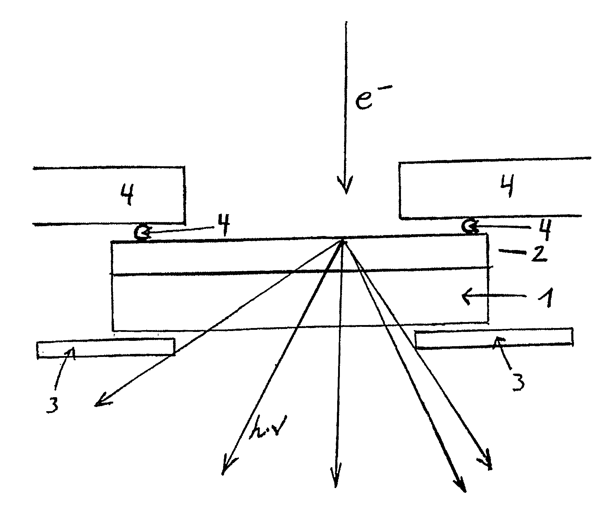
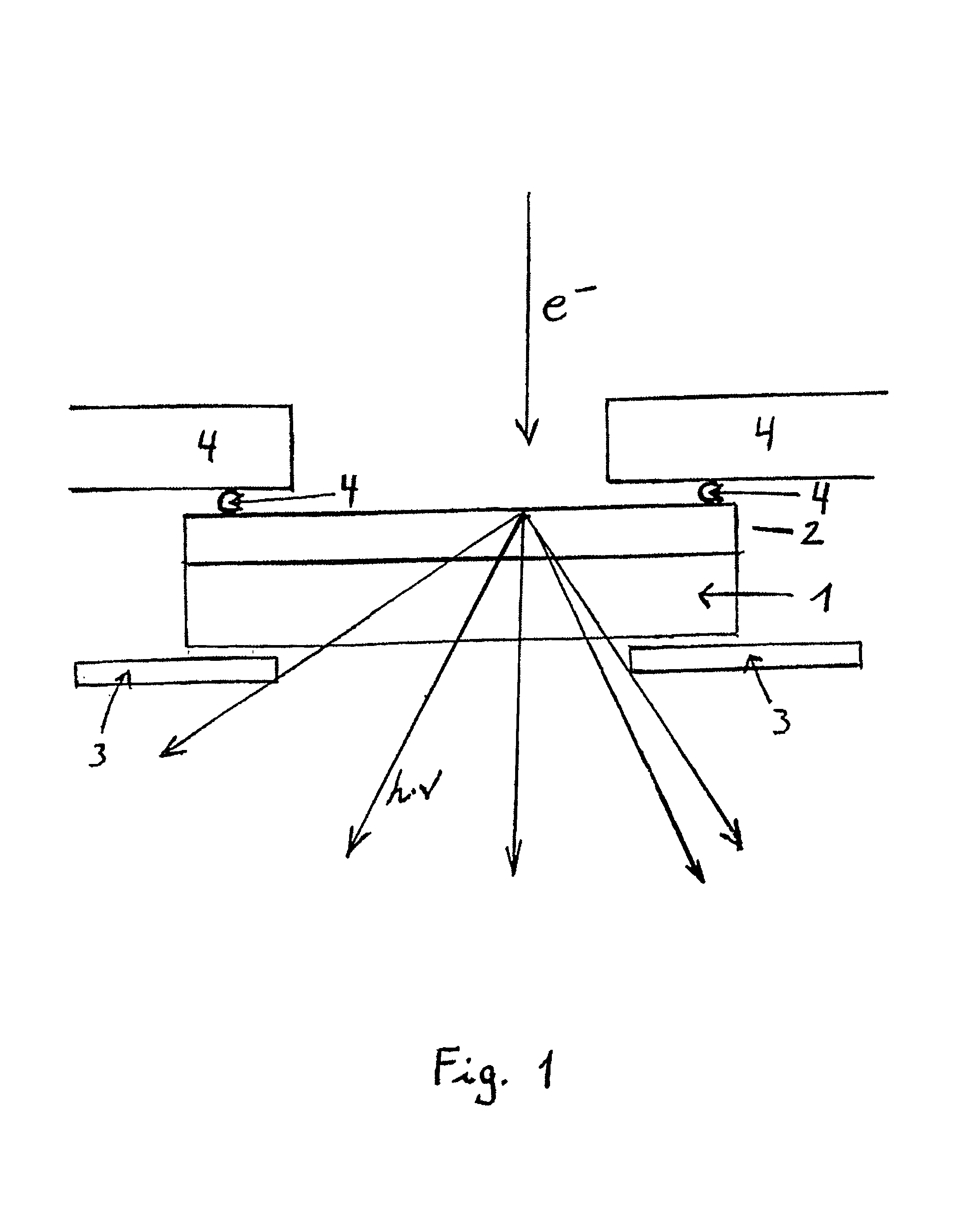
The technical effect of this patent is to provide an x-ray anode that is harmless and can be worked with at a smaller focus than previous designs. The anode material is located on a diamond window, which allows for better heat dissipation and a smaller focus diameter, resulting in higher radiation densities. The diamond window can be produced using chemical vapor deposition, and the thickness of the anode material can be controlled through a temperature sensor. The use of diamond as a window material makes it cost-efficient to overhaul the anode and reuse the diamond window. The excellent thermal conduction of diamond also allows for better optical resolution when examining temperature-sensitive samples.

Problems solved by technology

If the x-radiation produced is used for x-ray microscope purposes, this solution has the disadvantage of the resolution being only quite small because of the unavoidable ray divergence between the anode and the object to be imaged.
However, since thicker diamond windows are ruled out because of increased absorption by diamond, these thin diamond windows cause considerable mechanical problems.
Thin diamond windows can hardly withstand the pressure differential of approximately 105 Pa between the low pressure area and the outside area and have to be stabilized by appropriate crosspieces at considerable cost.
However, with a spot focus the problem arises that the energy generated by the electron bombardment causes the material to melt or evaporate, thus reducing its operating life.
However, a thick anode results in the x-radiation being absorbed by the anode material itself.
Moreover, this solution has the considerable disadvantage that mechanical problems can occur due to the existing pressure differentials, and the microfocus source can easily burst.
However, this is particularly harmful in the case of toxic beryllium, where a rupture of the microfocus source leads to undesirable apparatus down-time because of the safety measures for staff protection then required.
For these reasons according to prior art spot focussing is possible only to a limited extent.

Method used


Image

  • X-ray anode and process for its manufacture
  • X-ray anode and process for its manufacture

Examples


Embodiment Construction

The invention is based on the technical problem of producing an x-ray anode that avoids the disadvantages of the prior art as far as possible. The x-ray anode needs to be harmless from a health viewpoint and, in particular, should make it possible to work with a much smaller focus than with the prior art.

The solution of this technical problem is achieved through an anode material being located on a diamond window. The process-related task of producing such an x-ray anode includes coating an auxiliary layer with a diamond layer by chemical vapor deposition (CVD), and depositing a metallic layer on the diamond layer. Advantageous embodiments are provided in the dependent claims.

According to the invention it was recognized that the problems could be solved by an x-ray anode where the anode material is on a diamond window.

At first, diamond seems unsuitable as a material for a microfocus source. With an atomic number of Z=6, diamond absorbs x-radiation more than beryllium at Z=4. It woul...


PUM


Abstract

The invention relates to an x-ray anode and a process for its manufacture. The x-ray anode is characterized in that the anode material is embodied as a layer on a diamond window. The x-ray anode is preferably used with x-ray units which require as selective as possible x-radiation production to achieve as high as possible radiation intensity. Use in x-ray microscopes in which a high radiation intensity guarantees the highest resolutions is particularly preferred.

Description

BACKGROUND OF THE INVENTION1. Field of the InventionThe invention relates to an x-ray anode and a process for its manufacture. The x-ray anode according to the invention is preferred for use in x-ray units where the highest possible x-radiation is necessary. It is particularly preferred for use with x-ray microscopes in which a high radiation intensity guarantees the highest resolutions.2. Discussion of Background InformationIn x-ray production, metallic anode material is usually irradiated with electrons. The radiation caused by characteristic electronic transitions exits the apparatus through a window transparent for x-rays. In order to avoid absorption, X-ray production results here at low gas pressures. The transparent window serves to separate the low pressure area from the outside area.Metallic x-ray anodes made of e.g., copper or molybdenum, and a beryllium window in a target angle arrangement are known. There is a certain spacing between the anode and the beryllium window he...

Claims


Application Information

Patent Timeline
Patent Type & Authority Patents(United States)
IPC IPC(8): H01J35/18H01J35/10H01J35/00G21K5/08G21K5/00G21K7/00H01J9/14H01J35/08
CPCH01J35/10H01J35/18H01J2235/186H01J35/186G21K1/00
Inventor FRYDA, MATTHIASSCHAFER, LOTHARMATTHEE, THORSTON
Owner FRAUNHOFER GESELLSCHAFT ZUR FOERDERUNG DER ANGEWANDTEN FORSCHUNG EV
Why Eureka
Eureka Blog
Learn More