
Prosthetic implant and surgical tool

a technology for applied in the field of prosthetic implants and surgical tools, can solve the problems of inconvenient placement of inner hemispheres, damage to insertion tools, and insufficient force applied to impaction forces, and achieve good degree of rotational and axial control of implants, reduce the risk of unit damage during fitting, and good visibility of implants

Inactive Publication Date: 2004-06-08
T J SMITH & NEPHEW
View PDF29 Cites 85 Cited by
  • Summary
  • Abstract
  • Description
  • Claims
  • Application Information

AI Technical Summary

Benefits of technology

The solution provides a robust and secure attachment method that minimizes damage to the implant and tool, maintains visibility during surgery, and eliminates the need for multiple tool sizes, enabling precise control and easy adjustment of implant orientation.

Problems solved by technology

This feature cannot impinge upon the outside of the metal shell because the insertion tool may then become trapped between the shell and the bone.
As a result it is often not strong enough for the impaction forces applied.
This often results in damage to the insertion tool, or metal shell or both.
With this type of cup the inner hemisphere is not a convenient place to locate a mechanical feature for the insertion tool to grip on.
First, it would reduce the surface area of the prosthetic articulation.
Secondly, it could cause damage to the highly polished concave metal against which the ball of the patient's femur or the ball head of a femoral prosthesis is to bear.
Therefore, the provision of means for attaching an insertion tool to a prosthetic implant so that the attachment is sufficiently robust to withstand the impaction and other forces to which it may be subject during insertion of the prosthesis and yet which does not compromise the structural strength or the articulating properties of the prosthesis itself remains a problem in the art.
Another disadvantage of conventional tools is that they must be manufactured in a range of different sizes to receive acetabular cups or sheaths of the different sizes referred to above.
The difficulty of gripping and positioning prosthetic implants applies not only to acetabular implants but more generally to implants such as the tibial and femoral components of a prosthetic knee.

Method used


Image

  • Prosthetic implant and surgical tool
  • Prosthetic implant and surgical tool
  • Prosthetic implant and surgical tool

Examples


Embodiment Construction

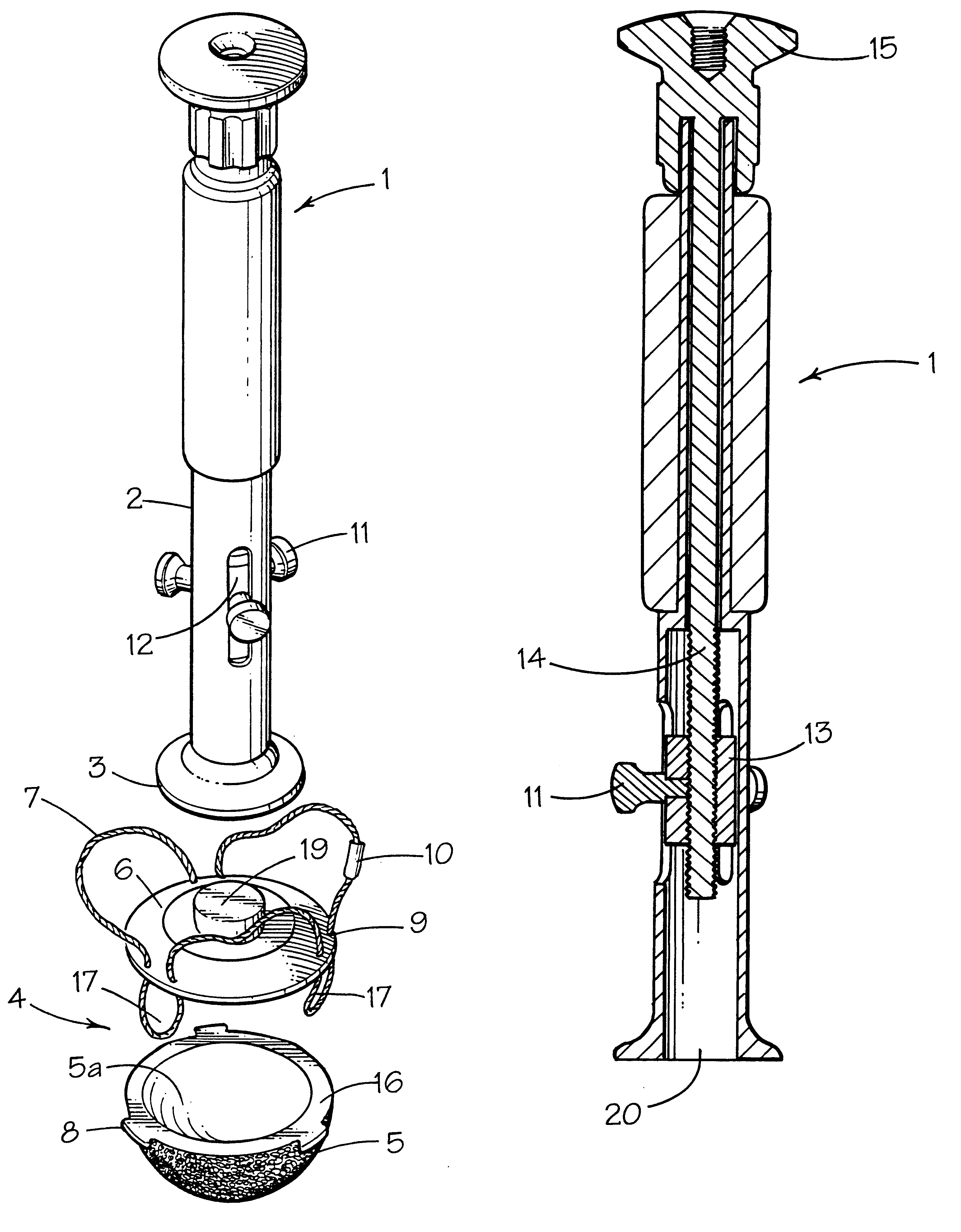
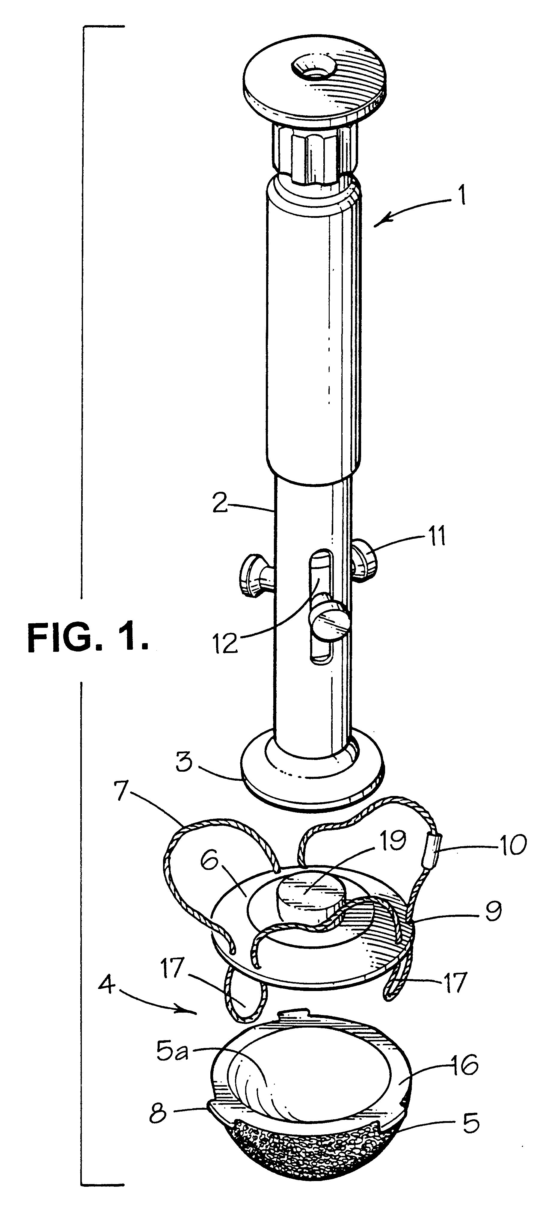
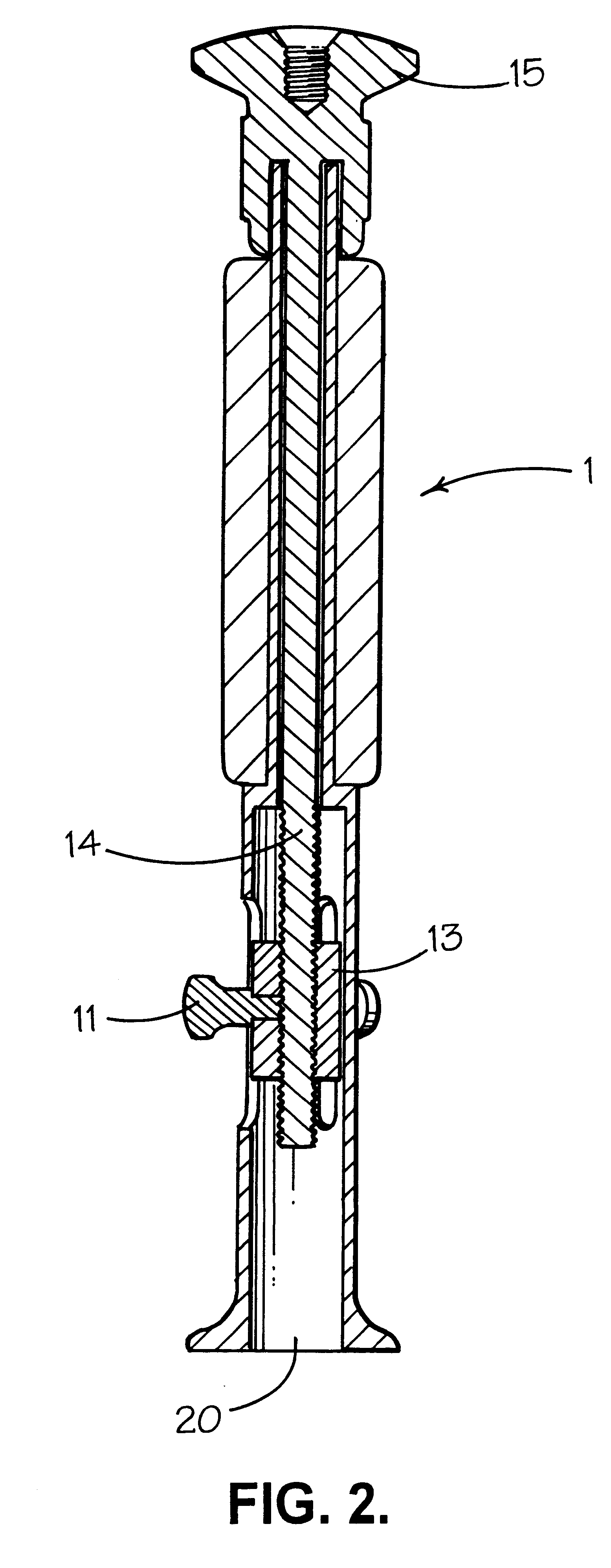
Referring to FIG. 1, there is shown a surgical tool 1 having an elongate body 2 and a first end surface 3 for bearing on a prosthetic implant 4.

Prosthetic implant 4 comprises a main body portion 5 which is an acetabular cup manufactured from cobalt chrome and intended for use as part of a metal on metal articulating joint. The inner articulating surface 5a of acetabular cup 5 is highly polished and is covered (when the implant is assembled in readiness for implantation in a prepared acetabular socket of a patient) by a disposable protective cover 6 which is manufactured from a plastics material such as polyethylene.

As will be apparent from the foregoing description, the provision of a disposable protective cover is a preferred feature of the invention. With the tool and prosthetic implant depicted in FIG. 1, the disposable protective cover 6 may, if desired, be omitted. In this case, end surface 3 of tool 1 would be provided with one or more flanges (not shown), or would itself be o...


PUM


Abstract

A surgical tool for gripping the implant includes an elongate body having a first end surface for bearing on the prosthetic implant. Lugs or hooked ends of the tool are capable of attaching the tool to the implant.

Description

1. FIELD OF THE INVENTIONThe present invention relates to a prosthetic implant and to a surgical tool for gripping the prosthetic implant during a surgical procedure.2. BACKGROUND OF THE INVENTIONThe replacement of all or a part of the bone surface of an articulation with a prosthetic implant has become a common surgical procedure. The procedure requires the surgeon to exercise both precision and delicacy in the placement of the prosthetic implant. However, it is frequently necessary for the surgeon also to exercise a degree of force, sometimes a vigorous force, in order to situate the prosthetic implant in a desired location on the bone surface.For example, in an operation to insert a prosthetic acetabulum in a patient's pelvis the surgeon first uses a reamer to grind a cavity of appropriate size in the patient's pelvis. The surgeon then inserts an acetabular cup into the cavity. By "appropriate size" is meant a size which is selected by the surgeon as being the most appropriate fo...

Claims


Application Information

Patent Timeline
Patent Type & Authority Patents(United States)
IPC IPC(8): A61F2/46A61F2/00A61F2/32A61F2/34A61F2/30
CPCA61F2/34A61F2/4609A61F2/0095A61F2/30767A61F2002/30225A61F2002/30462A61F2002/30718A61F2002/3411A61F2002/3419A61F2002/343A61F2002/4623A61F2002/4681A61F2220/0075A61F2230/0069A61F2310/00029A61F2310/00796A61F2/4603A61F2002/305A61F2002/3417
Inventor TUKE, MICHAEL ANTONYWOZENCROFT, ROBERT MICHAELPARSONS, ROBERT STEPHEN
Owner T J SMITH & NEPHEW
Learn More