
Hard carbon coating-clad base material

a technology of hard carbon coating and base material, which is applied in the direction of superimposed coating process, transportation and packaging, coatings, etc., can solve the problems of shortening the life of hard carbon coating, difficult to form hard carbon coating on the surface of any of various metal base materials, such as stainless steel base materials, and achieve excellent corrosion resistance, adhesion and abrasion resistance.

Inactive Publication Date: 2001-01-30
CITIZEN WATCH CO LTD
View PDF15 Cites 15 Cited by
  • Summary
  • Abstract
  • Description
  • Claims
  • Application Information

AI Technical Summary

Benefits of technology

The solution achieves excellent corrosion resistance, adhesion, and abrasion resistance on metals with poor corrosion resistance, such as brass and iron alloys, expanding the range of applicable base materials and improving the durability of the hard carbon coating.

Problems solved by technology

Therefore, the base material provided with the hard carbon coating formed by any of the above methods has such drawbacks that the adhesion between the hard carbon coating and the base material, especially when the base material is composed of a metal, is so poor that peeling or cracking is caused to shorten its life, or the formation of the hard carbon coating on the base material is infeasible.
That is, although the hard carbon coating can be formed on the surface of a silicon base material or a super hard material by any of the above methods, it is difficult to form the hard carbon coating on the surface of any of various metal base materials, such as stainless steel base materials.
Therefore, the problem exists that the types of the base materials on which the hard carbon coating can be formed are very limited.
However, still in the hard carbon coating-clad base material proposed in Japanese Patent Laid-Open Publication No. 149673 / 1990, the types of the base materials on which the hard carbon coating can be formed are limited.
For example, when brass is employed as the base material, dezincing from the brass occurs in a vacuum atmosphere due to the rise in the temperature inside the chamber at the time of the formation of the above intermediate layer or the formation of the hard carbon coating, so that the surface of the brass base material turn into orange peel to thereby lower the corrosion resistance of the surface of the base material and the adhesion between the brass base material and the hard carbon coating.
Therefore, the problem exists that, when brass is used as the base material of the hard carbon coating-clad base material proposed in Japanese Patent Laid-Open Publication No. 149673 / 1990, it is infeasible to fully utilize the excellent properties of the hard carbon coating.
Moreover, among iron materials Including a carbon Wool steel such as SK steel as defined in JIS G 4401 (1983), a martensitic stainless steel and ferritic stainless steel, when an iron material having poorer corrosion resistance than that of an austenitic stainless such as SUS 304 is used as the base material, corrosion due to rusting occurs in the base material after pre-wash to thereby cause the problem with respect to the adhesion between the base material and the hard carbon coating and the corrosion resistance of the hard carbon coating.

Method used


Image

  • Hard carbon coating-clad base material
  • Hard carbon coating-clad base material
  • Hard carbon coating-clad base material

Examples


example 1

First, a nickel-phosphorus alloy coating having a thickness of 0.5-1.0 .mu.m was formed as a substratal metal coating on a base material of SK steel having a length of 20 mm, a width of 25 mm and a thickness of 1 mm by an electroless nickel-phosphorus plating. This plating was performed in a plating bath having the following composition under the following plating conditions.

Subsequently, a titanium coating having a thickness of 0.1 .mu.m was formed on the nickel-phosphorus alloy coating by the sputtering process, and a silicon coating having a thickness of 0.3 .mu.m was similarly formed on the titanium coating, thereby forming a two-layer intermediate metal coating.

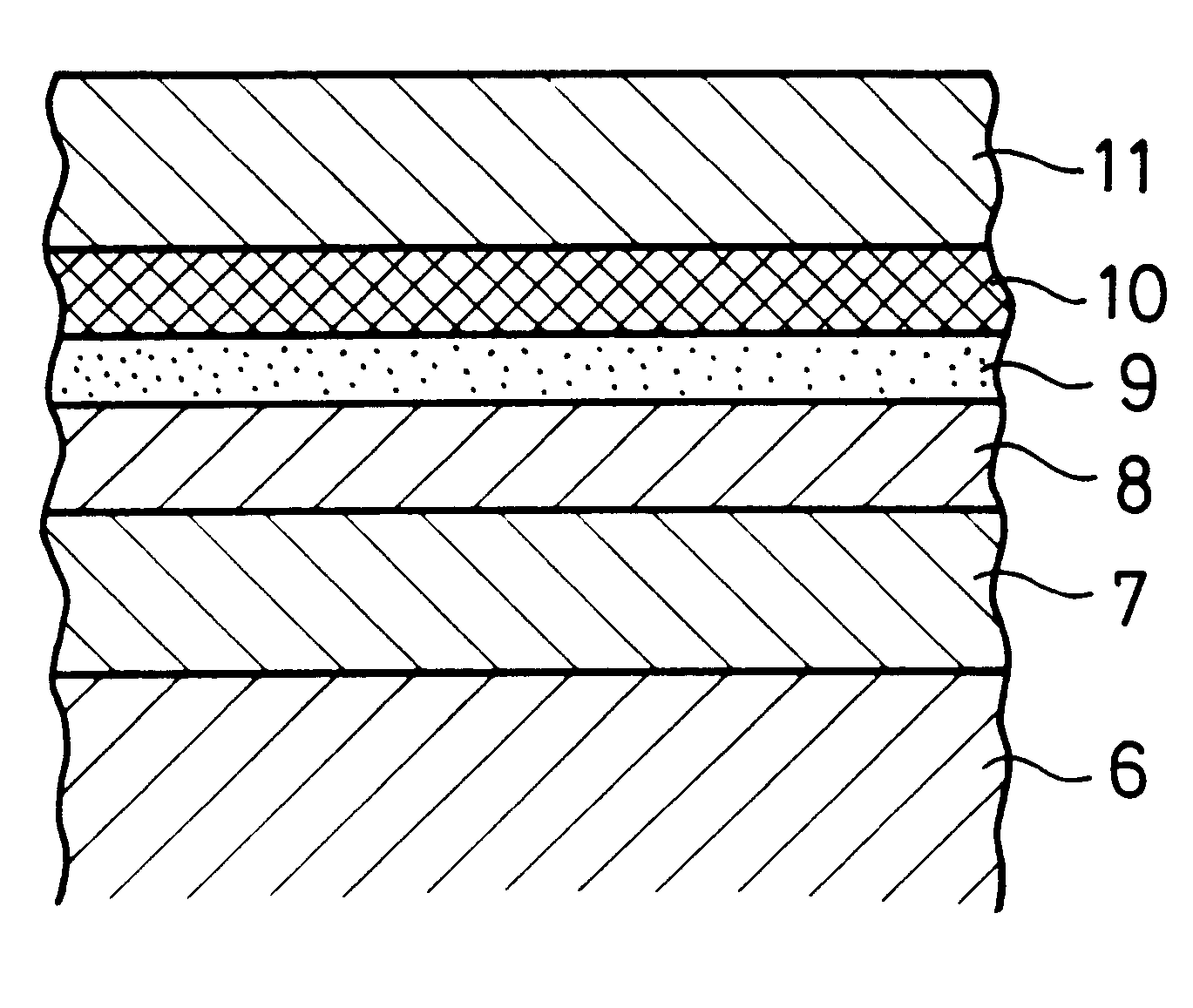
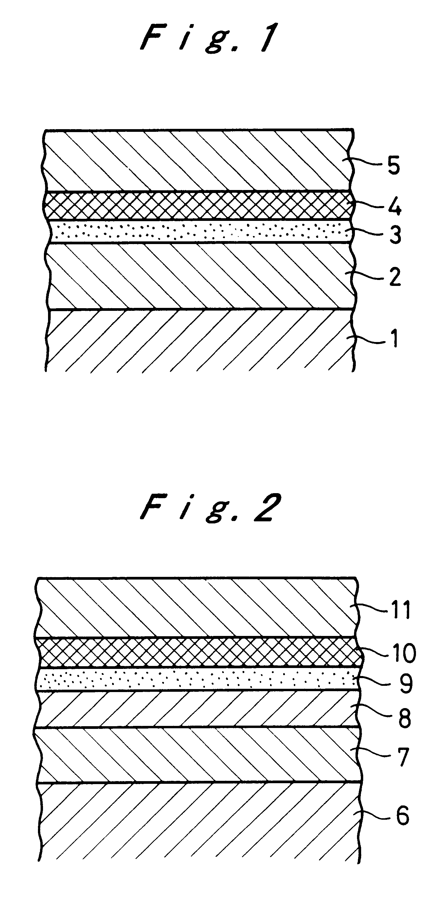
Thereafter, a hard carbon coating having a thickness of 2 .mu.m was formed on the above silicon coating according to the RFP-CVD process under the following conditions, thereby obtaining a hard carbon coating-clad base material having a structure shown in FIG. 1.

The thus obtained hard carbon coating-clad base material wa...

example 2

A hard carbon coating-clad base material having a structure as shown in FIG. 1 was obtained in the same manner as in Example 1, except that, after the formation of the nickel-phosphorus alloy coating, an aging treatment was conducted at 400.degree. C. for 60 minutes in non-oxidizing furnace, followed by the formation of the titanium coating.

The hardness of the above aged nickel-phosphorus alloy coating per se was 900 Nkgf / mm.sup.2 in terms of Vickers hardness (Hv), demonstrating that the aging treatment increased the hardness of the nickel-phosphorus alloy coating per se. In this connection, the hardness of the nickel-phosphorus alloy coating per se before the aging treatment was 350-400 Nkgf / mm.sup.2 in terms of Vickers hardness (Hv).

The thus obtained hard carbon coating-clad base material was subjected to the above CASS and artificial sweat immersion tests. In this Example, neither peeling nor corrosion was observed in the tests.

Further, the abrasion resistance test was performed,...

example 3

First, a nickel-phosphorus alloy coating having a thickness of 0.5-1.0 .mu.m was formed on a base material of brass having a length of 20 mm, a width of 25 mm and a thickness of 1 mm by the electroless nickel-phosphorus plating in the same manner as in Example 1.

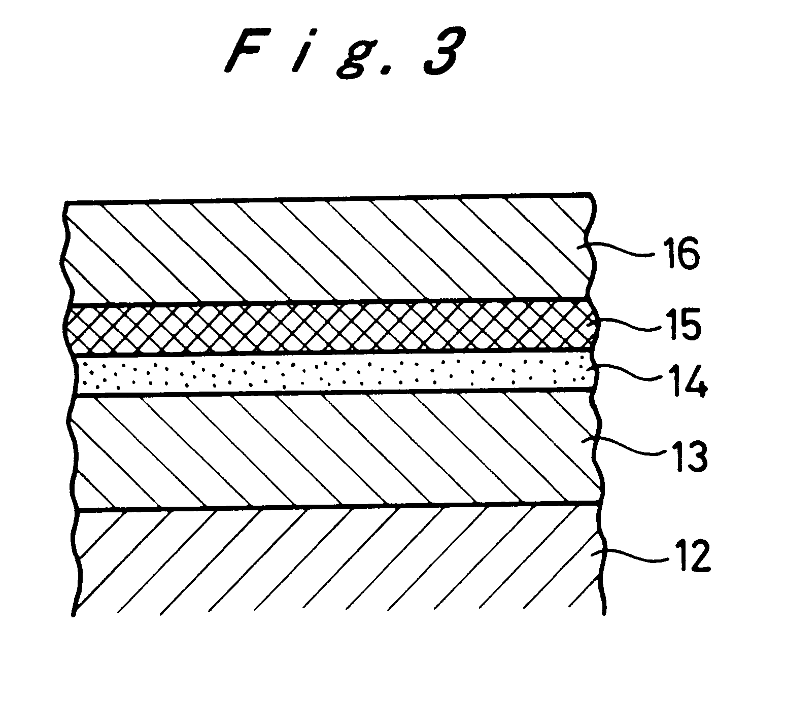
Subsequently, a chromium coating having a thickness of 0.5 .mu.m as another layer of the substratal metal coating was formed on the nickel-phosphorus alloy coating by a wet plating process. The wet plating was performed in a plating bath having the following composition under the following plating conditions.

Then, a titanium coating having a thickness of 0.1 .mu.m was formed on the chromium coating by the sputtering process, and a silicon coating having a thickness of 0.3 .mu.m was similarly formed on the titanium coating, thereby forming a two-layer intermediate metal coating.

Thereafter, a hard carbon coating having a thickness of 2 .mu.m was formed on the above silicon coating according to the same RFP-CVD process as in Ex...


PUM

PropertyMeasurementUnit
compressive stressaaaaaaaaaa
thicknessaaaaaaaaaa
thicknessaaaaaaaaaa

Abstract

The hard carbon coating-clad base material of the present invention comprises a base material, a substratal metal coating formed on the base material by a wet plating process, an intermediate metal coating comprising a titanium or chromium coating formed on the substratal metal coating by a dry plating process and a silicon coating formed on the titanium or chromium coating by a dry plating process, and a hard carbon coating formed on the silicon coating by a dry plating process. According to the present invention, a highly reliable hard carbon coating which is excellent in corrosion resistance, adhesion and abrasion resistance can be formed even on brass or an iron base material having poor corrosion resistance, such as SK steel and martensitic and ferritic stainless steels.

Description

The present invention relates to a hard carbon coating-clad base material. More particularly, the present invention relates to a hard carbon coating-clad base material in which an intermediate layer is provided between the base material and a hard carbon coating to thereby improve the adhesion with the hard carbon coating and the corrosion resistance.In recent years, the hard carbon coating is attracting attention because it has excellent properties, e.g., high hardness, high insulation, high thermal conductivity and chemical stability, similar to those of diamond. For the formation of the hard carbon coating, already, the physical vapor deposition method (hereinafter referred to as "PVD"), such as the ion beam method, the sputtering method and the ion plating method, the ECR (Electron Cyclotron Resonance) and the RF (Radio Frecuency) plasma chemical-vapor deposition method (hereinafter referred to as "RFP-CVD") have been brought into practical use.Generally, a compressive stress as...

Claims


Application Information

Patent Timeline
Patent Type & Authority Patents(United States)
IPC IPC(8): B32B15/04B32B9/00B32B9/06B32B15/00C23C28/00C25D5/10
CPCC23C28/321C23C28/343C23C28/322Y10T428/12944Y10T428/12854Y10T428/12812Y10T428/12674Y10T428/12875Y10T428/12806Y10T428/30Y10T428/12951Y10T428/12625Y10T428/12903Y10T428/1291Y10T428/12937
Inventor NAOI, KOICHI
Owner CITIZEN WATCH CO LTD
Learn More