Nuclear waste storage canisters and method of fabricating the same

Active Publication Date: 2021-07-08
HOLTEC INT
View PDF4 Cites 1 Cited by
  • Summary
  • Abstract
  • Description
  • Claims
  • Application Information

AI Technical Summary

Benefits of technology

The patent text describes a new and improved spent nuclear fuel canister that is more accessible and easy to open without the need for cutting. It also has improved heat rejection features to safeguard the fuel. The canisters maintain their small size and can be used interchangeably with existing designs without modification. The canister has a multi-thickness shell and a compact bolted closure lid-to-shell joint for ready access to the fuel contents inside. The canister is designed to withstand the high levels of heat and radiation exposure to workers during the retrieval process.

Problems solved by technology

Upon depletion and subsequent removal from the reactor, these spent nuclear fuel (“SNF”) rods are still highly radioactive and produce considerable heat, requiring that great care be taken in their subsequent packaging, transporting, and storing.
Specifically, the SNF emits extremely dangerous neutrons and gamma photons.
The all-welded canister provides guaranteed confinement of the contents, but makes the stored fuel difficult-to-access if repackaging is required at a later date.
While lid cutting tools to sever the lid from the canister shell have been successfully developed and demonstrated, the cutting operation is inherently dose-accretive, cumbersome, and time-consuming requiring metal chip and lubricant management during the process.
However, because of safety, space, and economic concerns, use of the pool alone is not satisfactory where the SNF needs to be stored for any considerable length of time.
Because the used fuel packaged in a canister is heat emitting (as much as 50 kilowatts, in some cases), most of the surface of the canister is heated which results in a concomitant reduction in the humidity of the air in contact with the external surface of the canister (as the air heats up, its relative humidity decreases).
More specifically, the most vulnerable portion of the shell is the region that is not sufficiently hot and hence in contact with humid air.
However, the results of this measure will not be known for a long time.
While the wide usage of austenitic stainless steel is grounded on its solid track record, a stainless weldment has one notable vulnerability: the material is susceptible to stress corrosion cracking (SCC) if its exposed surface has a tensile stress field and is subjected to a prolonged exposure to a salt-laden atmosphere such as a chloride or halide-bearing moist marine air of certain relative humidity.
However, the potential for eventual degradation has been sufficient to prompt the efforts to extend the canister's service life.
Austenitic stainless, however, has one drawback: while otherwise extremely resistant to general corrosion effects, it is somewhat vulnerable to stress corrosion cracking (SCC) under certain set of environmental conditions.
Canisters stored inside an outer ventilated module or overpack in a salt water environment may fulfill all of the above conditions most of the time, thereby making them vulnerable to the onset of SCC.
Such rolled cylindrical shell-type structures are further characterized by residual stresses from rolling as well as welding operations, further exacerbating the SCC problem.
The weld along the weld line is usually in a tensile state on the outer surface of the weld exposed to the ambient environment, which unfortunately makes it the prime location for SSC attack.

Method used


Image

  • Nuclear waste storage canisters and method of fabricating the same
  • Nuclear waste storage canisters and method of fabricating the same
  • Nuclear waste storage canisters and method of fabricating the same

Examples


first embodiment

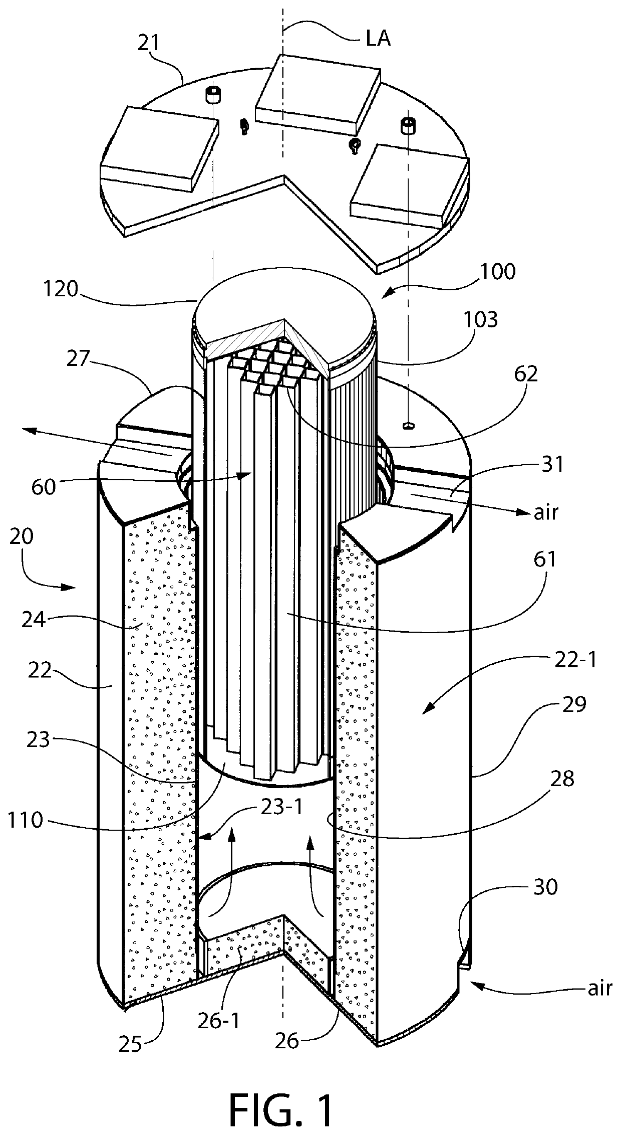
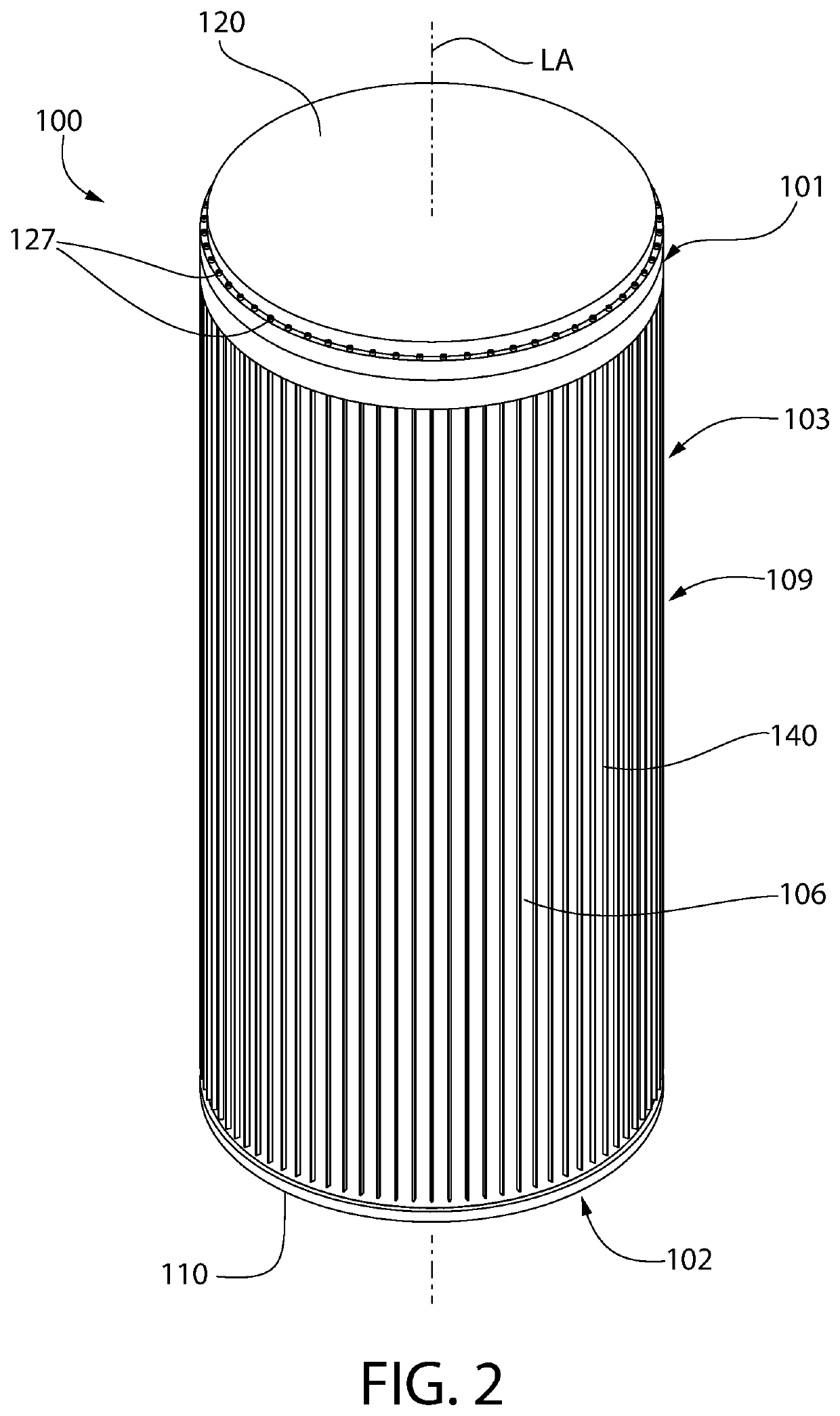
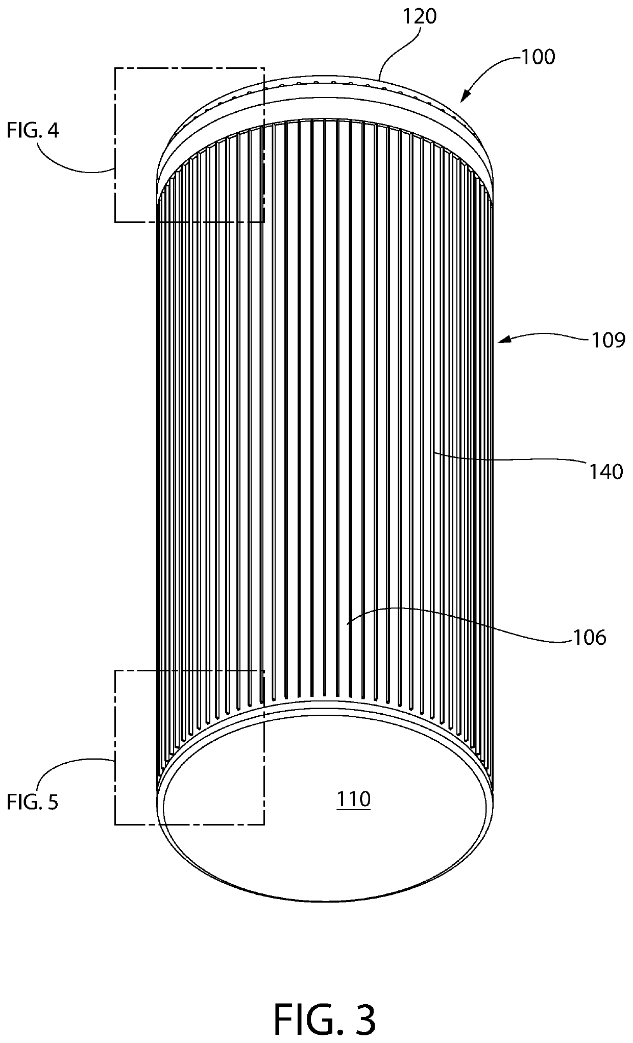
[0112]FIGS. 1-14 depict spent fuel canister 100 with compact bolted lid according to the present disclosure in further detail. The present canister advantageously comprises a bolted joint between the removable top closure lid and the canister body as previously described herein, thereby advantageously providing ready access to the SNF therein for repackaging or other purposes. The bolted lid joint is further described in the discussion which follows.

[0113]Canister 100 includes an elongated cylindrical body 103 comprising a single shell 106 including an open top 101, an open bottom 102, and sidewall 109 extending therebetween along a vertical longitudinal axis LA of the canister. Axis LA coincides with the geometric vertical centerline of the canister. Canister 100 further includes a bottom baseplate 110 and a top closure lid 120. Shell 106 may be of monolithic unitary structure in one embodiment formed of a single material.

[0114]Shell 106 further includes an inner surface 107 and op...

second embodiment

[0137]FIGS. 15-25 depict a spent nuclear fuel (SNF) canister 200 with compact bolted lid according to the present disclosure in further detail. SNF canister 200 is similar to canister 100. Similar parts will not be described in detail or numbered in the figures for the sake of brevity. There are some notable differences in design. For example, the shell 206 of canister 200 is substantially similar to shell 106 of canister 100 with exception that is does not have a step-shaped outer surface with annular recess. Instead, the inner surface of the shell is step shaped as further described below. In addition, canister 200 may be finless as shown, or alternatively may be equipped with external cooling fins if heat emitted by the SNF is considerable. Top closure lid 220 has a different configuration than lid 120 of canister 100; however, it retains the small profile bolted joint to the canister shell as further described below. In addition, lid 220 of canister 200 has a different sealing a...


PUM


Abstract

A dry storage systems for radioactive nuclear waste materials may include a double-walled canister system. The canister system may include a canister having a tubular inner shell defining an internal cavity for storing nuclear waste material, a first lid sealably welded to a first end of the inner shell, a primary base plate defining a peripheral edge portion and having an annular closure flange, and an annular full thickness butt weld formed at an abutment joint between the annular closure flange and a second end of the inner shell. The inner shell, first lid, and first end closure may collectively define a sealed primary pressure retention barrier. A tubular outer shell may adjoin the inner shell. The outer shell may be welded to the canister to form a hermetically sealed secondary pressure retention barrier.

Description

CROSS-REFERENCE TO RELATED APPLICATIONS[0001]This application is a continuation-in-part of U.S. patent application Ser. No. 16 / 695,450, filed Nov. 26, 2019, which claims the benefit U.S. Provisional Patent Application Ser. No. 62 / 772,986 filed Nov. 29, 2018.[0002]This application is also a continuation-in-part of U.S. patent application Ser. No. 15 / 294,896, filed Oct. 17, 2016, which claims the benefit of U.S. Provisional Patent Application Ser. No. 62 / 242,458, filed Oct. 16, 2015.[0003]This application is also a continuation-in-part of U.S. patent application Ser. No. 15 / 709,098, filed Sep. 19, 2017, which claims the benefit of U.S. Provisional Patent Application Ser. No. 62 / 396,565, filed Sep. 19, 2016.[0004]This application is also a continuation-in-part of U.S. patent application Ser. No. 16 / 116,994, filed August 30, 2018, which claims the benefit of U.S. Provisional Patent Application Ser. No. 62 / 551,914, filed Aug. 30, 2017.[0005]The entirety of each of the aforementioned appl...

Claims


Application Information

Patent Timeline
IPC IPC(8): G21F5/10G21F5/12G21F9/34G21F5/005
CPCG21F5/10G21F5/005G21F9/34G21F5/12Y02E30/30G21F9/36G21F5/012
Inventor SINGH, KRISHNA P.BULLARD, II, CHARLES W.
Owner HOLTEC INT
Why Eureka
Try Eureka