
Ratchet-based ion pumping membrane systems

a technology of ion pumping membrane and ratchet, which is applied in the field of ion pumping, can solve the problems of large solvent amounts, few synthetic technologies that rely on ions for sensing and signaling, power generation and energy storage, and large amounts of solvents, and achieve energy efficient effects

Pending Publication Date: 2020-12-24
RGT UNIV OF CALIFORNIA
View PDF0 Cites 2 Cited by
  • Summary
  • Abstract
  • Description
  • Claims
  • Application Information

AI Technical Summary

Benefits of technology

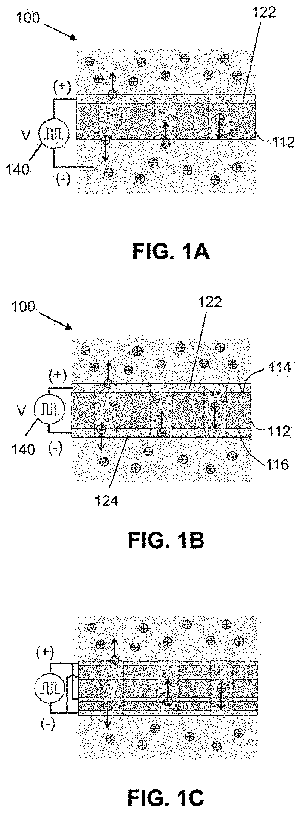
The present invention is an ion pump that uses an electronic ratchet mechanism. This electronic ratchet mechanism is designed to remove the need to drive redox reactions, which is required in commercial electrodialysis. As a result, the present invention does not waste any voltage on undesired redox reactions, avoids corrosion caused by redox, and does not generate redox products that could affect the water sources. Additionally, the ion pump allows for continuous operation, unlike in capacitive deionization which must stop the water flow after switching the water flow streams from saline to desalted. Overall, the invention is more efficient, effective, and reliable for producing a stable flow of desalination.

Problems solved by technology

Although widely used in Nature, there are very few synthetic technologies that rely on ions for sensing and signaling, power generation, and energy storage and use.
However, application of an external bias to induce ionic current flow results in an enrichment or depletion of ions in regions of the sub-10 nm charged pores and ultimately ionic current rectification.
Non-electrical separations processes have drawbacks in that typically they require large amounts of solvents to provide the medium for classical separations or the addition of chemical species, such as chelates or sorbents, to the water in order to change the properties of dissolved species and alter their solubility in a phase.
Requiring additional soluble chemical species complicates this otherwise simplistic design and often times is a nonstarter for separations technologies because the added chemical species may not be compatible with desired processes or ultimate uses, e.g. adding molecules to drinking water.

Method used


Image

  • Ratchet-based ion pumping membrane systems
  • Ratchet-based ion pumping membrane systems
  • Ratchet-based ion pumping membrane systems

Examples


example

[0100]The following is a non-limiting example of the present invention. It is to be understood that said example is not intended to limit the present invention in any way. Equivalents or substitutes are within the scope of the present invention.

[0101]EPIIR Simulations

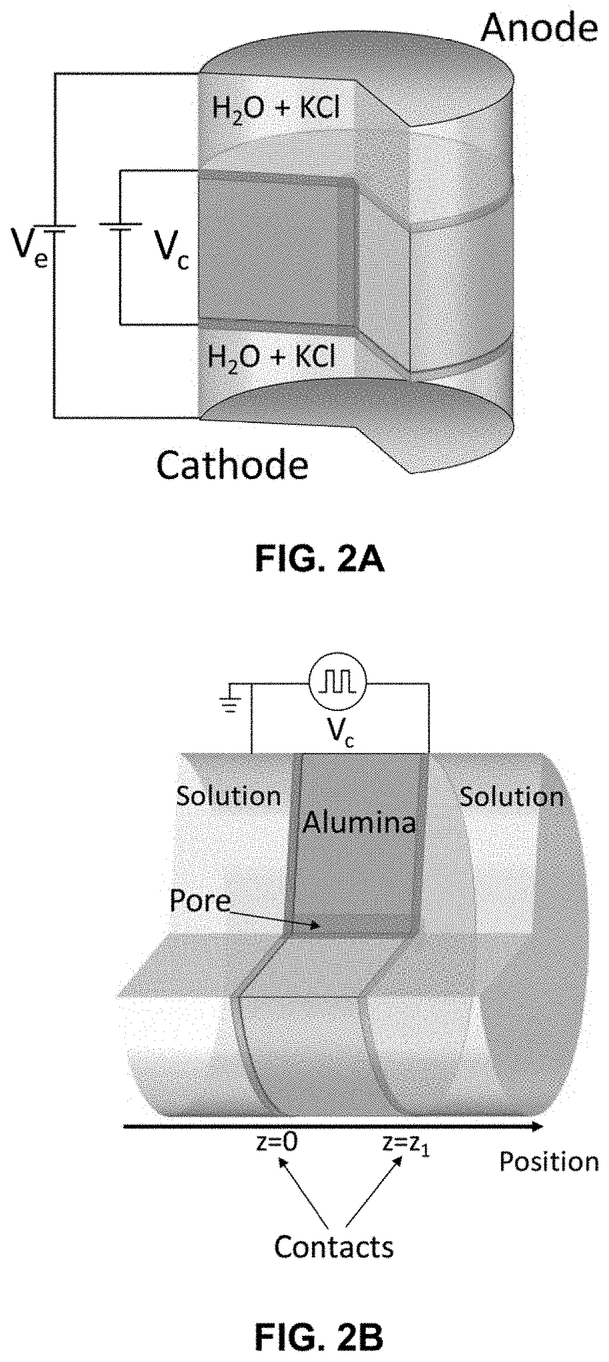
[0102]The EPIIR theoretical pumping performance was estimated in two stages. First, the potential distribution within the device was calculated using finite elements simulations (COMSOL Multiphysics). Next, the potential distribution obtained in the finite elements simulation was used as an input in an analytic computation to obtain the net ratchet current.21,31 The finite element simulation domain consisted of a single pore in an AAO wafer and the electrolyte around it. FIG. 2A shows a schematic illustration of the simulation domain. The solid region is assumed to be made of perfectly insulating alumina and the pore and electrolyte compartments on both sides of the EPIIR are filled with 1 mM KCl aqueous solution where ...


PUM


Abstract

Described herein is an ion pump system implementing an electronic ratchet mechanism produced by modulating a spatially varying electric potential distribution that can result in a net ionic current and voltage. The ion pumping membrane system includes an ion-permeable layer integrated with ion-selective membranes. The electric potential distribution within the ion-permeable layer is modulated through external stimuli. When immersed in solution, ions within the ion-permeable layer experience a time varying, spatially asymmetric electric field distribution resulting in ratchet-driven direction pumping, which can be used in applications such as desalination.

Description

CROSS-REFERENCES TO RELATED APPLICATIONS[0001]This application is a non-provisional and claims benefit of U.S. Patent Application No. 62 / 863,761, filed Jun. 19, 2019, the specification(s) of which is / are incorporated herein in their entirety by reference.STATEMENT REGARDING FEDERALLY SPONSORED RESEARCH OR DEVELOPMENT[0002]This invention was made with government support under Grant No. DE-AC02-05CH11231 and DE-SC0004993 awarded by the Department of Energy. The government has certain rights in the invention.BACKGROUND OF THE INVENTIONField of the Invention[0003]The present invention relates to ion pumps, namely, to devices that implement ratchet-based mechanisms to pump ions.Background Art[0004]Ion pumps are devices that use power to introduce a net ionic flux. For example, in cell membranes, nanoscale channels transduce the free energy available from adenosine triphosphate (ATP) hydrolysis to pump different types of ions against a gradient in their electrochemical potential. In natur...

Claims


Application Information

Patent Timeline
IPC IPC(8): H01J41/12B01D61/46C02F1/469
CPCB01D2313/365B01D61/46H01J41/12C02F2103/08C02F1/4693C02F1/469B01D69/02Y02A20/124B01D61/463
Inventor ARDO, SHANESEGEV, GIDEONTOMA, FRANCESCAAGER, JOELKAUTZ, RYLANLARSON, DAVID
Owner RGT UNIV OF CALIFORNIA
Learn More