
Power equipment fault detecting and positioning method of artificial intelligence inference fusion

a technology of artificial intelligence and positioning method, which is applied in the direction of instruments, testing/monitoring control systems, biological models, etc., can solve the problems of poor robustness of conventional monitoring diagnosis methods, inability to meet, and inability to accurately detect the fault of power equipment, etc., and achieves the effect of high accuracy

Active Publication Date: 2020-12-10
WUHAN UNIV
View PDF1 Cites 66 Cited by
  • Summary
  • Abstract
  • Description
  • Claims
  • Application Information

AI Technical Summary

Benefits of technology

The multi-source information fusion method in this patent allows for more accurate fault identification and positioning in power equipment through the use of artificial intelligence inference fusion. This method combines information from multiple sensors, resulting in higher accuracy than a single deep learning diagnosis method.

Problems solved by technology

The connection among industrial equipment is becoming closer and closer, and a fault of any important parts may lead to breakdown of the entire system.
The conventional monitoring diagnosis methods exhibit poor robustness and can hardly satisfy the characteristics of a large capacity, multi-source heterogeneity, and a high acquisition frequency of the intelligent monitoring system data.
Moreover, diagnosis techniques such as fuzzy diagnosis, the expert system, and the support vector machine are overdependent on manmade parameter feature setting and are thus less efficient in the environment where the monitoring items are complex.
However, none of the above methods considers the fault position information, and the research on the deep learning positioning method as applied to the power equipment fault diagnosis is almost still blank.

Method used


Image

  • Power equipment fault detecting and positioning method of artificial intelligence inference fusion
  • Power equipment fault detecting and positioning method of artificial intelligence inference fusion
  • Power equipment fault detecting and positioning method of artificial intelligence inference fusion

Examples


Embodiment Construction

[0028]To provide a further understanding of the purposes, technical solutions, and advantages of the invention, the invention will be further described in detail below with reference to the accompanying drawings and embodiments. It is understood that the specific embodiments described herein are merely meant to illustrate, rather than limit, the invention.

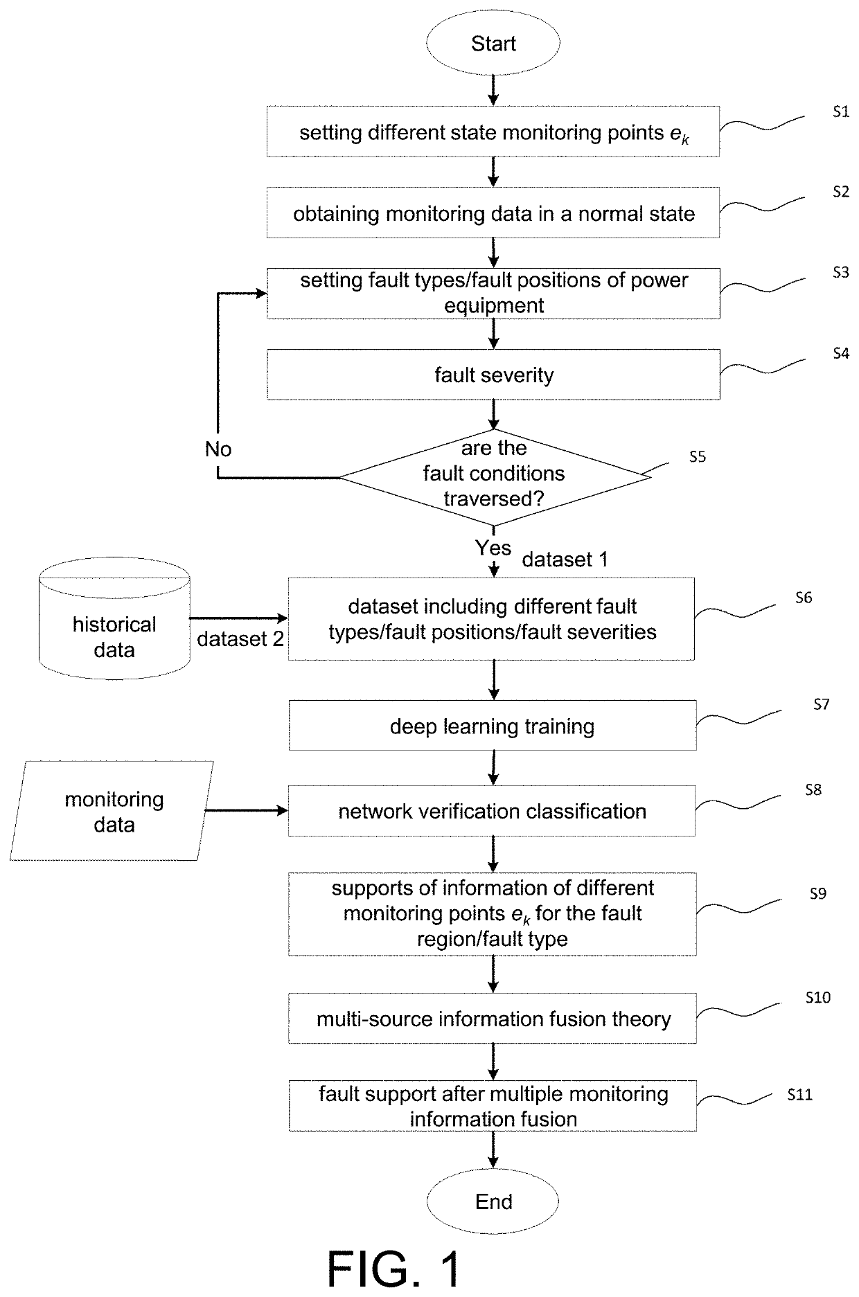
[0029]As shown in FIG. 1, a power equipment fault detecting and positioning method of artificial intelligence inference fusion according to the present embodiment specifically includes the following steps:

[0030]S1: setting state monitoring points ek of the power equipment;

[0031]S2: obtaining monitoring data of different monitoring points in a normal operating state of the power equipment;

[0032]S3: setting fault types and fault positions of the power equipment, and obtaining monitoring information of the different monitoring points;

[0033]S4: setting a range of fault severity according to actual requirements to determine an interval ...


PUM


Abstract

A method includes steps: 1) obtaining monitoring information of different monitoring points in normal state of power equipment; 2) setting faults and obtaining monitoring information of different fault types, positions, monitoring points of the equipment; 3) taking the monitoring information obtained in steps 1) to 2) as training dataset, taking the fault types and positions as labels, inputting the training dataset and the labels to deep CNN for training; 4) collecting monitoring data, performing verification and classification using step 3), obtaining probability values corresponding to each of the labels; 5) taking classification results of different labels as basic probability assignment values, with respect to a monitoring system composed of multiple sensors, taking different sensors as different evidences for decision fusion, performing fusion processing using the DS evidence theory to obtain fault diagnosis result. The invention can intelligently realize fault detection, fault type determination, and fault positioning of the power equipment.

Description

CROSS-REFERENCE TO RELATED APPLICATION[0001]This application claims the priority benefit of China application serial no. 201910486614.8, filed on Jun. 5, 2019. The entirety of the above-mentioned patent application is hereby incorporated by reference herein and made a part of this specification.BACKGROUND OF THE INVENTIONField of the Invention[0002]The disclosure relates to a power equipment fault detecting and positioning method of artificial intelligence inference fusion, and more particularly, to a power equipment fault diagnosis method combining the deep convolutional neural network and the multi-source information fusion theory.Description of Related Art[0003]With the advent of the Industry 4.0 era, the equipment will continue to develop toward intelligence and integration in the future. The connection among industrial equipment is becoming closer and closer, and a fault of any important parts may lead to breakdown of the entire system. Therefore, it is necessary to thoroughly ...

Claims


Application Information

Patent Timeline
Patent Type & Authority Applications(United States)
IPC IPC(8): G06N3/08G06K9/62G06N5/04G06F1/3206G06V10/764G06V10/80
CPCG06N5/04G06N3/08G06K9/6259G06K9/6232G06K9/6288G06F1/3206G06K9/6267G06N3/045G06F18/25G06F18/214G06F18/213G06N5/043G05B23/024G05B23/0281G06V10/82G06V10/764G06V10/80G06N3/042G06N7/01G06F18/2413H02J13/00002H02J3/0012G01R31/08G06F18/24G06F18/2155
Inventor HE, YIGANGDUAN, JIAJUNZHANG, HUIHE, LIULU
Owner WUHAN UNIV
Learn More