
Reactive coating material for steel material providing high corrosion resistance

Inactive Publication Date: 2020-09-17
KYOTO MATERIALS +1
View PDF0 Cites 0 Cited by
  • Summary
  • Abstract
  • Description
  • Claims
  • Application Information

AI Technical Summary

Benefits of technology

The present invention provides a coating material that can protect steel and other materials from corrosion in various environments, including acidic and chloride-rich environments. The coating film and protective film produced from this material offer high resistance to corrosion.

Problems solved by technology

However, the stainless steel has many restrictions in uses for structures and machines for reasons that it is expensive; also has problems in terms of corrosion resistance such as occurrence of pitting corrosion due to being a high-alloy steel, and the like; and has deterioration in mechanical properties such as strength, toughness, and the like, as compared with a low-alloy steel; and others reasons.
However, there were problems in that it took as long a period of time as approximately ten years or longer for the weather-resistant steel before formation of the protective rust; floating rust or flowing rust of red rust, yellow rust, or the like occurred due to corrosion at an initial stage in the above period of time, which was not only unfavorable in appearance but also caused remarkable damages such as a decrease in a plate thickness due to corrosion, and the like.
In particular, in an acidic environment or a severe corrosive environment including chlorides, protective rust was not even formed and sufficient corrosion resistance was not secured in some cases.
However, the coating cannot prevent the progress of corrosion resulting from deterioration of a coating film or defects of the coating film even in an ordinary corrosive environment, and only slows down the progress of corrosion.
For example, there is a coating means exhibiting an high anti-corrosion property, such as a zinc-rich primer, a zinc-rich paint, or the like using a sacrificial anti-corrosion action with zinc dust, but this can only exert the effect restrictively in a relatively short period of time, and thus, the progress of corrosion resulting from deterioration of the coating film or defects of the coating film cannot be essentially prevented.
In addition, in a case where a content of zinc dust is increased or the coating film is thickened in an attempt to increase the sacrificial anti-corrosion effect, remarkable damages in adhesiveness to or workability with a steel material are resulted.
The coating material disclosed in these literatures is different from the above-mentioned coating materials which cannot prevent the progress of corrosion resulting from deterioration of a coating film or defects of the coating film.

Method used


Image

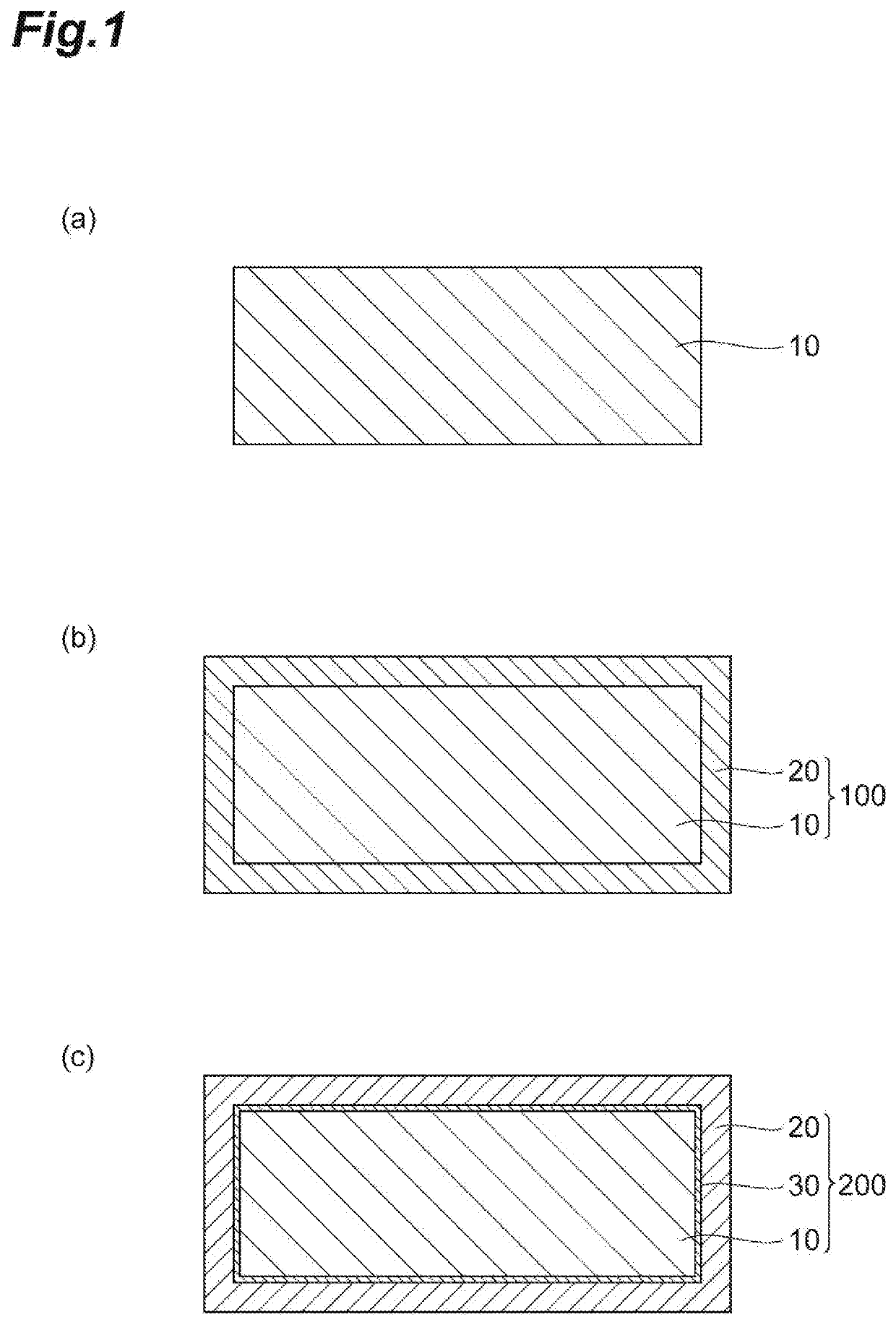
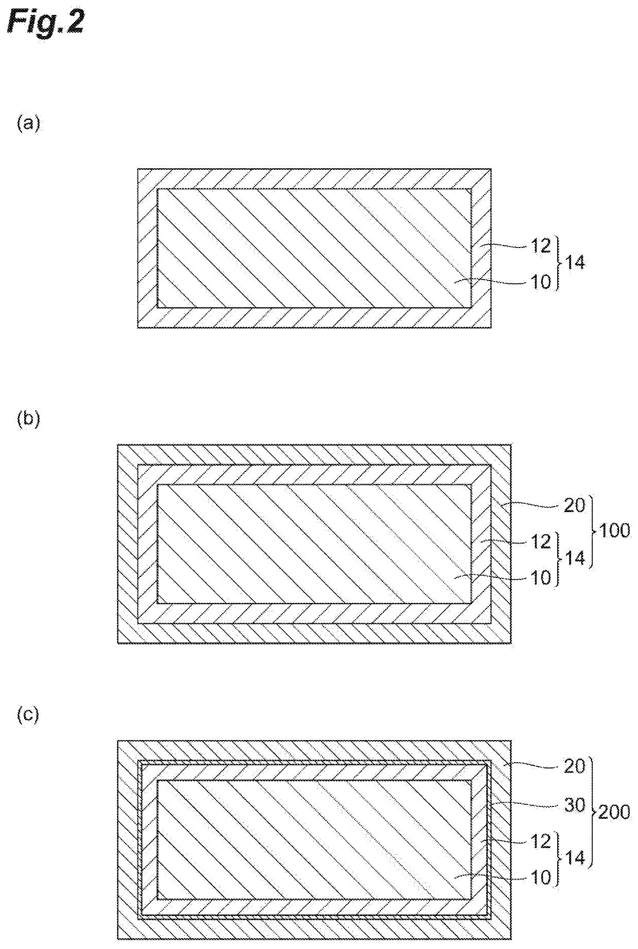
  • Reactive coating material for steel material providing high corrosion resistance
  • Reactive coating material for steel material providing high corrosion resistance

Examples


example 1

[0100]

[0101]0.05 parts by mass of barium hydroxide, 5 parts by mass of aluminum sulfate, 5 parts by mass of nickel sulfate, 5 parts by mass of magnesium sulfate, 10 parts by mass of an extender / coloring pigment, and 74.95 parts by mass of a polyvinyl butyral resin (a resin X shown in Table 4) were mixed with appropriate amounts of xylene, toluene, and isopropyl alcohol so that a viscosity of the coating material was 200 to 1,000 cps at 20° C., thereby obtaining a coating material. Further, the extender / coloring pigment is formed of barium sulfate and calcium carbonate as the extender pigment, and red iron oxide, carbon (inorganic pigments), and phthalocyanine blue (organic pigment) as the coloring pigment, respectively, in which both the pigments were included at equivalent parts by mass. The compositions of the solid content of the coating material are shown in Table 5.

[0102]

[0103]A specimen (I) shown in Table 1 below, having a dimension of 30×25×5 mm, was prepared. Table 1 shows t...

examples 731 to 750

[0110]A coating material of Examples 731 to 750 was obtained in the same manner as in Example 1, except that the composition of the coating material was changed to those described in Table 78 and Table 79. Incidentally, the amount of the solvent in the coating material was appropriately adjusted so that the viscosity of the coating material at 20° C. as determined using a B-type viscometer was 200 to 1,000 cps. In addition, in Examples 731 to 750, coated steel materials for an acid resistance test and a chloride resistance test were obtained in the same manner as in Example 1, except that the specimen of the steel material, the pretreatment method, and the thickness of the coating film were changed to those described in Table 78 and Table 79 to form a coating film, and a topcoating film (corresponding to the layer of (A)) provided by further applying topcoating materials onto the coating film so that the thickness and the moisture permeability were as described in Table 78 and Table...

examples 751 to 760

[0111]A coating material of Examples 751 to 760 was obtained as shown in Table 80 in the same manner as in Example 204, and thus, a coating film was formed on a surface of a specimen. The amount of a solvent in the coating material was appropriately adjusted so that the viscosity of the coating material at 20° C. as determined using a B-type viscometer was 200 to 1,000 cps. In addition, in Examples 751 to 760, coated steel materials for an acid resistance test and a chloride resistance test were obtained in the same manner as in Example 204, except that a topcoating film (corresponding to the layer of (B) in Examples 751, 753, 755, 757, and 759, and corresponding to the layer of (C) in Examples 752, 754, 756, 758, and 760) provided by applying a topcoating material having the composition described in Table 81 onto the coating films with the thickness and the resin system as described in Table 80, respectively, was formed.


PUM

PropertyMeasurementUnit
Temperatureaaaaaaaaaa
Percent by massaaaaaaaaaa

Abstract

Provided is a coating material including barium oxide and / or barium hydroxide, and a metal sulfate, wherein a soluble amount of the metal sulfate in 100 g of water is 0.5 g or more at 5° C.

Description

TECHNICAL FIELD[0001]The present invention relates to a reactive coating material for a steel material providing high corrosion resistance, and a coating film and a protective film, each obtained using the same. The present invention more specifically relates to a coating material for enhancing corrosion resistance of a steel material by application to a steel material, a steel material covered with a rust layer due to oxidation.corrosion, or a steel material covered with an organic layer or an inorganic layer (hereinafter sometimes collectively simply referred to as a steel material), and a coating film and a protective film. Further, the steel material mentioned herein also encompasses a steel material coated with zinc, aluminum or an alloy (hereinafter referred to as a plated metal) having the same as a main component (hereinafter referred to as a plated steel material).BACKGROUND ART[0002]It is generally known that when an oxide layer having a high environmental barrier property...

Claims


Application Information

Patent Timeline
IPC IPC(8): C09D5/10C09D7/61C23F11/04C23C22/08
CPCC23F11/04C09D5/10C09D7/61C23C22/08C23C28/00C09D5/084C09D5/103C09D5/106C09D7/41C09D7/69C09D129/14C08K2003/2206C08K2003/3045C08K2003/3081C09D7/20B05D1/02B05D3/0406B05D7/54B05D2202/10B05D2601/20C08K2003/0812C08K2003/0893C08L63/00C09D179/02C09D163/00C08K3/014C08K3/14C08L79/02C08K3/22C08K3/30C09D5/08C09D201/00C23C26/00C23F11/00
Inventor YAMASHITA, MASATOKUWANO, SATOSHIITOKAWA, ATSUSHINANJO, SHINICHIROYANAGI, SHOGO
Owner KYOTO MATERIALS
Learn More