
Machine Learning System and Data Fusion for Optimization of Deployment Conditions for Detection of Corrosion Under Insulation

a machine learning and optimization technology, applied in the field of inspection technologies, can solve problems such as difficult detection of cui, corrosion cannot be easily observed, and moisture buildup that infiltrates the insulation material, and achieve the effects of improving the detection efficiency of cui, improving the detection efficiency, and improving the detection efficiency

Active Publication Date: 2020-03-05
SAUDI ARABIAN OIL CO +1
View PDF0 Cites 3 Cited by
  • Summary
  • Abstract
  • Description
  • Claims
  • Application Information

AI Technical Summary

Benefits of technology

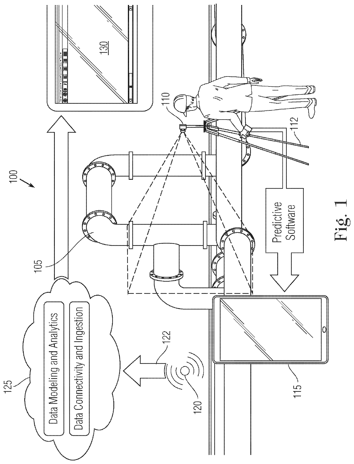
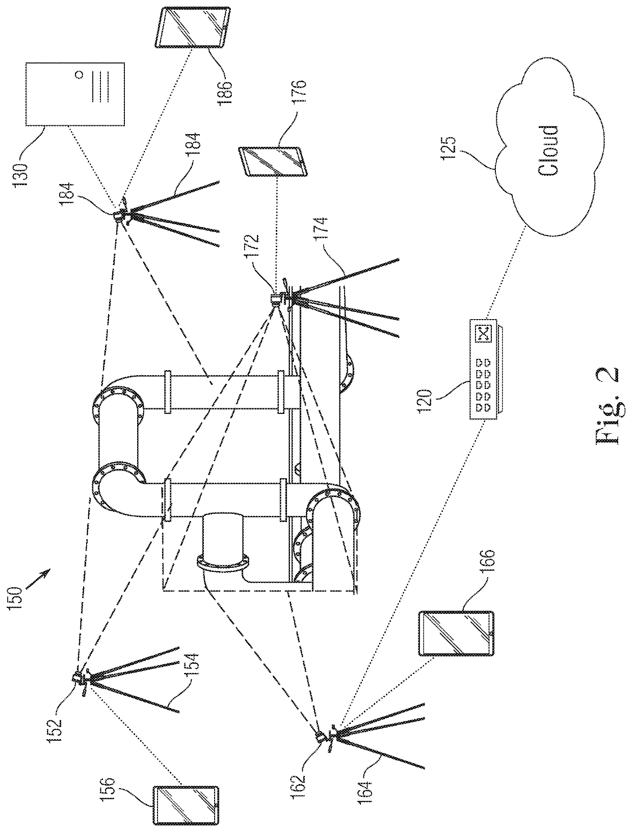
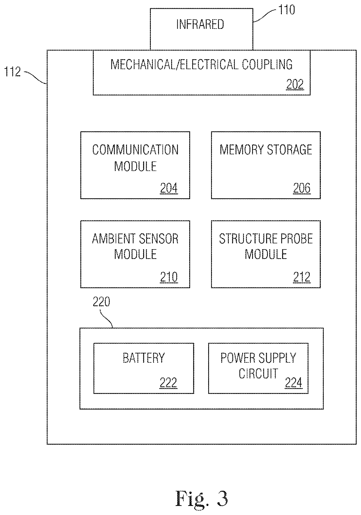
The present invention provides a system for predicting and detecting corrosion under insulation (CUI) in an infrastructure asset using machine learning and data fusion. The system includes an infrared camera and a smart mount mechanically supporting and electrically coupling the camera. The smart mount has a communication module, memory storage, a battery module, an ambient sensor module, and additional sensors for obtaining CUI-related data. The system also includes a computing device with a processor executing a machine learning algorithm using the thermal images, ambient condition data, and CUI-related data from the camera and smart mount. The performance of the machine learning algorithm is tested by testing the deployment conditions of the camera and smart mount. The deployment conditions include the time of year, time of day, position, orientation, image capture duration, and number of images captured per time period. The invention also provides a method for optimizing the deployment conditions of the investigative kit for obtaining data from the asset to enable prediction and detection of CUI. The performance of the machine learning algorithm is measured based on corrosion prediction accuracy, cost of deployment and testing, and speed of deployment and testing.

Problems solved by technology

As the corrosion cannot be easily observed due to the insulation covering, which typically surrounds the entire structure, CUI is challenging to detect.
The typical causes of CUI are moisture buildup that infiltrates into the insulation material.
Water can accumulate in the annular space between the insulation and the metal surface, causing surface corrosion.
Sources of water that can induce corrosion include rain, water leaks, and condensation, cooling water tower drift, deluge systems and steam tracing leaks.
While corrosion usually begins locally, it can progress at high rates especially if there are repetitive thermal heating and / or cooling cycles or contaminants in the water medium or surrounding air such as chloride or acid.
When CUI is undetected, the results of can lead to the shutdown of a process unit or an entire facility and can lead to catastrophic incidents.
Removal of insulation can be a time-consuming and costly process, while the accuracy of NDT techniques can be insufficient due to the large number of variables (e.g., geometrical, environmental, material-related), that cause false positives (incorrect detection of corrosion) and false negatives (incorrect non-detection of corrosion) in the detection process.
Additionally, many facilities have elevated networks of pipes that are difficult to access, requiring scaffolding for visual inspection.
Due to these challenges, it has been found that localized visual inspections of assets are not reliably effective at detecting CUI, and they do not reflect conditions of the assets.
There is a related technical gap in predictive risk assessment of CUI.

Method used


Image

  • Machine Learning System and Data Fusion for Optimization of Deployment Conditions for Detection of Corrosion Under Insulation
  • Machine Learning System and Data Fusion for Optimization of Deployment Conditions for Detection of Corrosion Under Insulation
  • Machine Learning System and Data Fusion for Optimization of Deployment Conditions for Detection of Corrosion Under Insulation

Examples


Embodiment Construction

[0029]Embodiments of the present invention provide a predictive approach for detecting corrosion under insulation (CUI) taking into account dependent and independent surrounding variables. Thermal images of investigated assets are captured over time.

[0030]As a series of thermal images of the same or overlapping area(s) are captured over time, changes in phenomena can be readily observed, including the impact of temporary issues such as wind. The thermal images can provide several types, or orders, of temperature information that can be indicative of locations vulnerable to CUT. The first order of temperature information is regular temperature (T) data revealed by the color shown in the thermal images. The second order of temperature information is changes in temperature (ΔT), such as the contrasts shown between different regions, and a third order of information is rate of change in temperature analytics (df(T) / dt) as determined by analysis of a series of images over time. Additiona...


PUM

PropertyMeasurementUnit
thermalaaaaaaaaaa
corrosion prediction accuracyaaaaaaaaaa
speedaaaaaaaaaa

Abstract

A system for predicting corrosion under insulation (CUI) in an infrastructure asset includes at least one infrared camera positioned to capture thermal images of the asset, at least one smart mount supporting and electrically coupled to the at least one infrared camera and including a wireless communication module, memory storage, a battery module operative to recharge the at least one infrared camera, an ambient sensor module adapted to obtain ambient condition data and a structural probe sensor to obtain CUI-related data from the asset. At least one computing device has a wireless communication module that communicates with the at least one smart mount and is configured with a machine learning algorithm that outputs a CUI prediction regarding the asset. A cloud computing platform receive and stores the received data and the prediction output and to receive verification data for updating the machine learning algorithm stored on the computing device.

Description

CROSS-REFERENCE TO RELATED APPLICATIONS[0001]This application is a continuation-in-part of commonly-assigned and co-pending U.S. patent application Ser. No. 16 / 117,937 ('937 application), filed on Aug. 30, 2018 and entitled “Cloud-based machine learning system and data fusion for the prediction and detection of corrosion under insulation, which is hereby incorporated by reference as if set forth in its entirety herein.FIELD OF THE INVENTION[0002]The present invention relates to inspection technologies, and, more particularly, relates to a hardware and software-based system for the prediction and detection of corrosion under insulation (CUI).BACKGROUND OF THE INVENTION[0003]Corrosion under insulation (CUI) is a condition in which an insulated structure such as a metal pipe suffers corrosion on the metal surface beneath the insulation. As the corrosion cannot be easily observed due to the insulation covering, which typically surrounds the entire structure, CUI is challenging to detect...

Claims


Application Information

Patent Timeline
Patent Type & Authority Applications(United States)
IPC IPC(8): G06T7/00G01N17/00G06N20/00G06K9/62
CPCG01N17/00G06T2207/10048G06T2207/30136G06T7/0004G06N20/00G06K9/6288G01N25/72G06N3/08G06N3/044G06F18/25
Inventor AL SHEHRI, ALILIM, SER NAMAMER, AYMANUZUNBAS, MUSTAFAALDABBAGH, AHMADABABTAIN, MUHAMMADCUNNINGHAM, VINCENTBOOT, JOHNCHAN, GODINE KOK YAN
Owner SAUDI ARABIAN OIL CO
Learn More